Magnetic memory device using in-plane current and electric field

Inactive Publication Date: 2015-08-20
KOREA UNIV RES & BUSINESS FOUND
View PDF7 Cites 20 Cited by
  • Summary
  • Abstract
  • Description
  • Claims
  • Application Information

AI Technical Summary

Benefits of technology

[0033]The magnetic memory device according to the present disclosure may reverse magnetization of a free magnetic layer by using an external magnetic field and a spin-hall spin-torque generated at the free magnetic layer when a current flows along a conductive wire adjacent to the free magnetic layer and also selectively induce a flux reversal to a specific cell by changing magnetic anisotropy of a magnetic layer included in each cell by means of a voltage applied to each magnetic memory cell. In a flux reversal by a spin-hall spin-torque, the critical current density is proportional to perpendicular magnetic anisotropy and volume of the magnetic layer, similar to an existing configuration, but is also proportional to an amount of spin current with respect to the applied current generated by the spin-hall effect.
[0034]Therefore, when reducing a volume of the device for high density integration of the device, perpendicular magnetic anisotropy may be increased to ensure thermal stability, and an amount of generated spin current may be effectively increased to reduce a critical current density. In other words, the memory device of the present disclosure may ensure thermal stability and satisfy a critical current density simultaneously.
[0035]In addition, since a current for generating a spin-hall spin-torque to reverse magnetiz

Problems solved by technology

If an external magnetic field is used instead of current in order to control magnetization of the free magnetic layer, a half-selected cell problem becomes serious as the device has a smaller size, and thus there is a limit in high density integration of the device.
Meanwhile, if a spin transfer torque generated by applying a current is used to the device, flux reversal of the cell may be easily induced regardless of the size of the device.
This may result in undesired deletion of recorded magnetic data.
Since both Δ and JC are proportional to Koff in case of inducing a flux reversal using a spin transfer torque in the basic structure depicted in FIG. 1, it is very difficult to satisfy sufficiently high Δ and sufficiently low JC simultaneously in

Method used


Image

  • Magnetic memory device using in-plane current and electric field
  • Magnetic memory device using in-plane current and electric field
  • Magnetic memory device using in-plane current and electric field

Examples


experimental example 1

Presence or Absence of a Flux Reversal of the Free Magnetic Layer According to a Current and a Magnetic Field Applied to the Device of the Present Disclosure

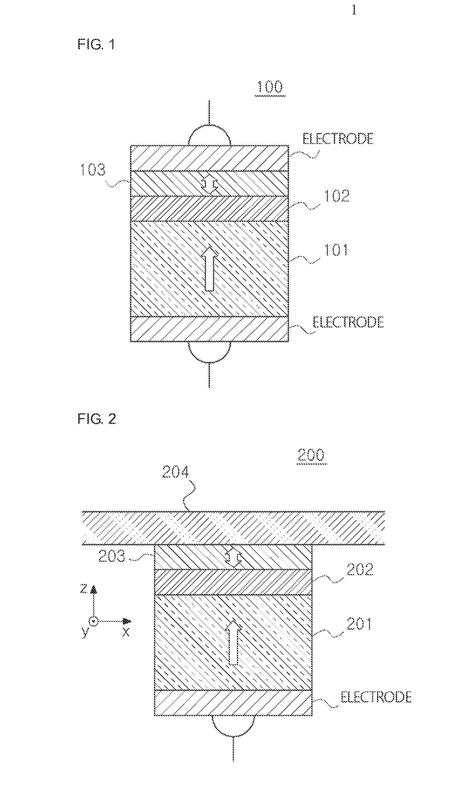
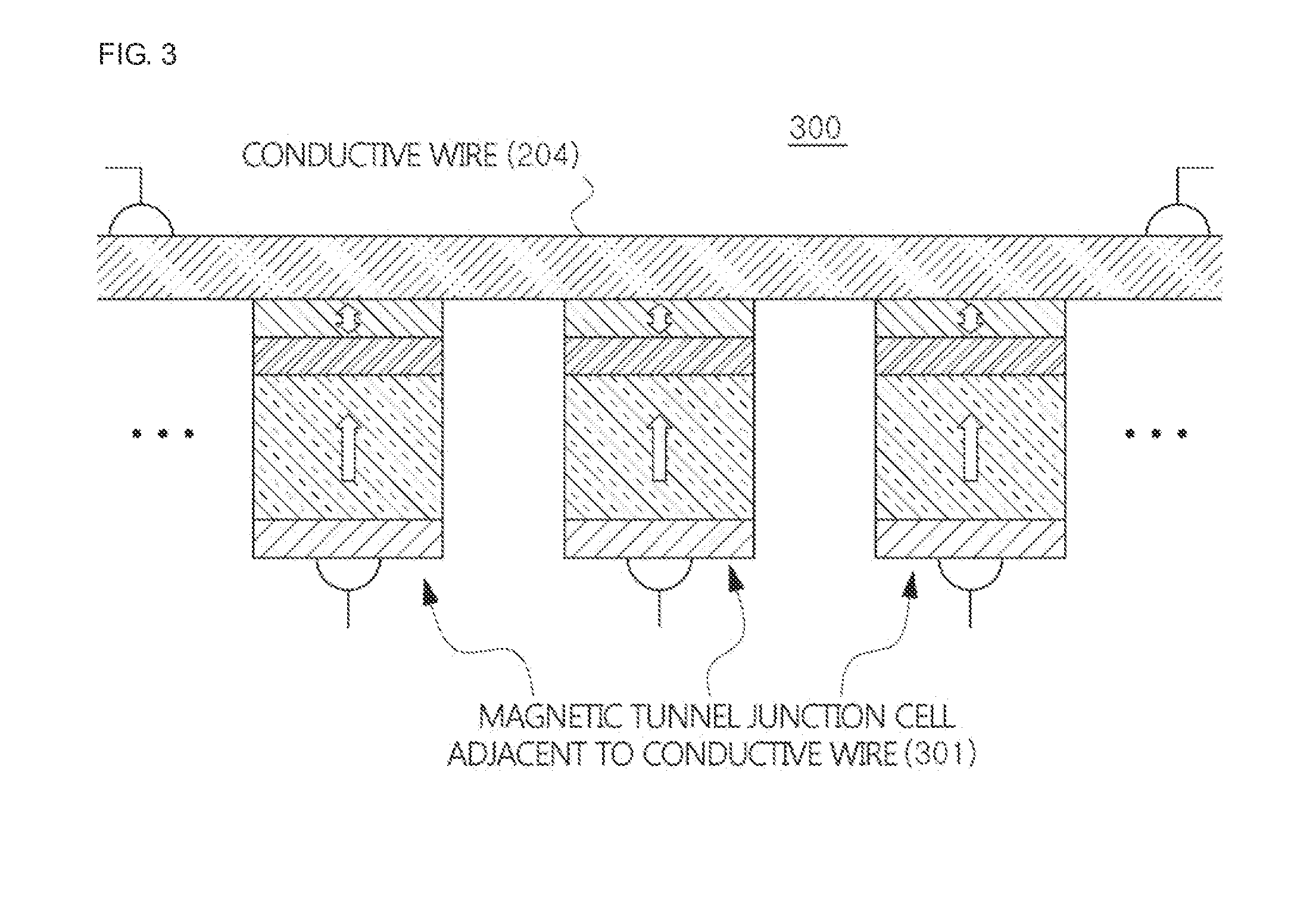
[0070](1) As shown in FIG. 3, if each cell of the magnetic memory device according to an embodiment of the present disclosure is selected using a voltage or not selected, the presence or absence of a flux reversal of the free magnetic layer is determined depending on various in-plane currents applied to the conductive wire 204 and a magnetic field applied from the outside.

[0071](2) Structure and properties of the device are as follows.

[0072]Cross-sectional area of the entire structure=400 nm′

[0073]Free magnetic layer 203: thickness (t)=2 nm, perpendicular magnetic anisotropy constant (K⊥)=8×10⁶ erg / cm3, saturation magnetization (MS)=1000 emu / cm3, Gilbert damping constant (α)=0.1, spin-hall angle (θSH)=0.3′

[0074](3) FIG. 4a is a graph showing a presence or absence of a flux reversal of a free magnetic layer according to a current...


PUM


Abstract

Provided is a magnetic memory device for applying an in-plane current to a conductive wire adjacent to a free magnetic layer having a perpendicular magnetic anisotropy to induce a flux reversal of the free magnetic layer and simultaneously applying a voltage to each magnetic tunnel junction cell selectively to reverse magnetization of the free magnetic layer selectively at each specific voltage. The magnetic memory device may implement high density integration by reducing a volume since a spin-hall spin-torque causing a flux reversal is generated at an interface of the conductive wire and the free magnetic layer, ensure thermal stability by enhancing perpendicular magnetic anisotropy of the magnetic layer, and reduce a critical current density by increasing an amount of spin current. In addition, by increasing tunnel magnetic resistance with a thick insulating body, the magnetic memory device may increase a reading rate without badly affecting the critical current density.

Description

TECHNICAL FIELD[0001]The following disclosure relates to a magnetic memory device using a magnetic tunnel junction, and more particularly, to a magnetic memory device for applying an in-plane current to a conductive wire adjacent to a free magnetic layer having a perpendicular magnetic anisotropy to induce a flux reversal of the free magnetic layer and simultaneously applying a voltage to each magnetic tunnel junction cell selectively to reverse magnetization of the free magnetic layer selectively at each specific voltage.BACKGROUND ART[0002]A ferromagnetic body means a material which is spontaneously magnetized even though a strong magnetic field is not applied thereto from the outside. In a magnetic tunnel junction structure (including a first magnetic body, an insulating body and a second magnetic body) in which an insulating body is interposed between two ferromagnetic bodies, a tunnel magneto resistance effect in which an electric resistance varies depending on relative magneti...

Claims


Application Information

Patent Timeline
IPC IPC(8): H01L27/22H01L43/08H01L43/10H01L43/02
CPCH01L27/222H01L43/10H01L43/08H01L43/02G11C11/1675G11C11/161G11C11/18H01L29/40111G11C11/16Y10S977/935H10B61/00H10N50/10H10N50/01H10N50/80H10N50/85
Inventor LEE, KYUNG-JINLEE, SEO-WON
Owner KOREA UNIV RES & BUSINESS FOUND
Why Eureka
Try Eureka