Multi mode bias modulator operating in envelope tracking mode or average power tracking mode and envelope tracking power amplifier using the same

a multi-mode bias modulator and power amplifier technology, applied in the field of power amplifiers, can solve the problems of poor efficiency in the back-off region lower than the maximum power point, poor efficiency in the average power, and inability to significantly improve the overall system efficiency, so as to minimize the complexity of the circuit, improve efficiency, and improve efficiency

Active Publication Date: 2015-08-20
RES & BUSINESS FOUND SUNGKYUNKWAN UNIV
View PDF9 Cites 57 Cited by
  • Summary
  • Abstract
  • Description
  • Claims
  • Application Information

AI Technical Summary

Benefits of technology

[0016]At least some embodiments of the present invention are directed to the provision of a multi-mode bias modulator capable of improving efficiency in a wide power region and an envelope tracking power amplifier using the same.
[0017]At least some embodiments of the present invention are directed to the provision of a multi-mode bias modulator capable of improving efficiency even at lower output power while minimizing the complexity of a circuit and an envelope tracking power amplifier using the same.

Problems solved by technology

Although these power amplifiers can operate with high efficiency in a compression region, i.e., in a saturation region, they require an additional linearization technique due to the non-linearity of the compression region and do not significantly improve efficiency in terms of an overall system.
Furthermore, these power amplifiers operate with high efficiency in the saturation region, but have poor efficiency in a back-off region lower than a maximum power point.
Wireless communication systems operate in the back-off region lower than the PAPR during most of their operating time, thus resulting in poor efficiency in average power.
In other words, when an output bias voltage modulated by the bias modulator is low because the size of an envelope is small, the power efficiency of the bias modulator is also low.
However, this method is problematic in that the linear amplifier should be designed to operate desirably at all different operating voltages and both a circuit size and power consumption are increased due to the added DC-DC converter.

Method used


Image

  • Multi mode bias modulator operating in envelope tracking mode or average power tracking mode and envelope tracking power amplifier using the same
  • Multi mode bias modulator operating in envelope tracking mode or average power tracking mode and envelope tracking power amplifier using the same
  • Multi mode bias modulator operating in envelope tracking mode or average power tracking mode and envelope tracking power amplifier using the same

Examples


Embodiment Construction

[0040]With regard to embodiments of the present invention disclosed herein, specific structural and functional descriptions are given merely for the purpose of illustrating the embodiments of the present invention. Embodiments of the present invention may be practiced in various forms, and the present invention should not be construed as being limited to embodiments disclosed herein.

[0041]Embodiments of the present invention will be described in detail below with reference to the accompanying drawings. The same reference numerals will be used to denote the same components throughout the accompanying drawings, and redundant descriptions of the same components will be omitted.

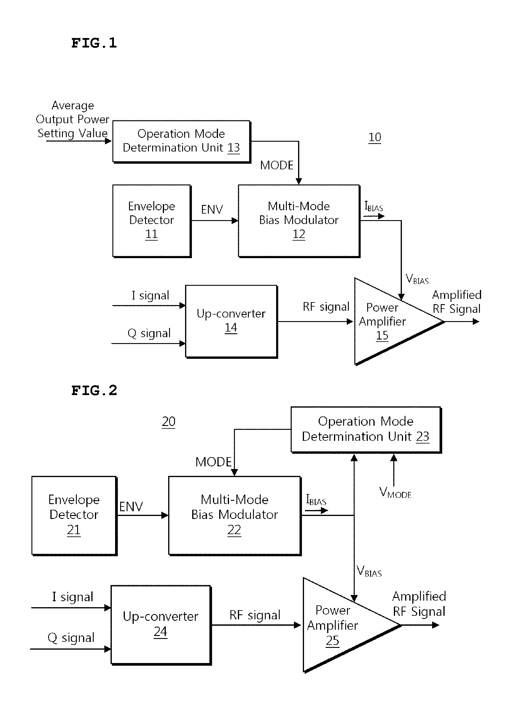
[0042]FIG. 1 is a block diagram of an envelope tracking power amplifier according to an embodiment of the present invention.

[0043]Referring to FIG. 1, the envelope tracking power amplifier 10 may include an envelope detector 11, a multi-mode bias modulator 12, an operation mode determination unit 13, an up-conver...


PUM


Abstract

A multi-mode bias modulator operating in envelope tracking mode or average power tracking mode and an envelope tracking power amplifier using the same are disclosed. The envelope tracking power amplifier includes a multi-mode bias modulator and a power amplifier. The multi-mode bias modulator generates a variable bias voltage using a linear amplifier and a switching amplifier operating in envelope tracking mode or average power tracking mode in accordance with an operation mode control signal that determines any one of envelope tracking mode and average power tracking mode. The power amplifier is biased in response to the variable bias voltage, power-amplifies a radio frequency (RF) signal, and outputs the amplified RF signal to an antenna.

Description

CROSS-REFERENCE TO RELATED APPLICATION[0001]This application claims the benefit under 35 U.S.C. 119(a) of Korean Patent Application No. 10-2014-0019119, filed on Feb. 19, 2014, in the Korean Intellectual Property Office, the entire disclosures of which are incorporated herein by reference for all purposes.BACKGROUND[0002]1. Technical Field[0003]The present invention relates generally to a power amplifier, and, more particularly, to an envelope tracking power amplifier[0004]2. Description of the Related Art[0005]Recent wireless communication systems utilize a modulation method having a high peak to average power ratio (PAPR), such as orthogonal frequency division multiplexing (OFDM), in order to process a large amount of data while efficiently utilizing limited frequency resources.[0006]In a modulation method having a high PAPR, a high-efficiency power amplifier, such as a class C, D, E or F power amplifier, may be used as a power amplifier (PA) in order to maximize efficiency. Altho...

Claims


Application Information

Patent Timeline
Patent Type & Authority Applications(United States)
IPC IPC(8): H03F1/02H03F3/217H03F3/21H03F3/19
CPCH03F1/0227H03F3/217H03F2200/102H03F2200/451H03F1/0205H03F1/0211H03F1/0222H03F1/305H03F3/19H03F3/211H03F2200/507H03F2203/21127H03G3/20
Inventor YANG, YOUNGOOHAM, JUNGHYUNJUNG, HEARYUN
Owner RES & BUSINESS FOUND SUNGKYUNKWAN UNIV
Why Eureka
Try Eureka