System and method for monitoring and diagnosing patient condition based on wireless sensor monitoring data

a wireless sensor and patient technology, applied in the field of system and method for monitoring and diagnosing patient condition based on wireless sensor monitoring data, can solve the problems of icds that can also have lead failures after being worn by patients, limiting factors of implantable devices, and other undesirable effects on the quality of life of patients, so as to improve the generation of ecg data

Inactive Publication Date: 2015-08-27
PEERBRIDGE HEALTH
View PDF10 Cites 44 Cited by
  • Summary
  • Abstract
  • Description
  • Claims
  • Application Information

AI Technical Summary

Benefits of technology

[0017]The method may further include applying a second sensor, similar to the first sensor, onto the skin of the subject. In such embodiments, at least one of the external device and the first circuit is configured to generate at least five-lead ECG data from ECG data obtained from the first sensor and ECG data obtained from the second sensor. The first sensor and the second sensor may form a cluster to enable enhanced generation of ECG data.

Problems solved by technology

However, there can be limiting factors for these implantable devices such as inaccuracy in detecting the relevant heart condition episodes and administering appropriate therapies.
ICDs can also have lead failures after being worn by a patient for an extended period of time, e.g., a number of years.
Lead positioning errors and failures can cause inaccurate or distorted electrograms, and thereby may lead to insufficient, overly aggressive, or otherwise inappropriate cardiac intervention, such as excessive number of unwarranted shocks or shocks with unnecessarily large magnitude, which can cause discomfort, pain, and other undesirable effects on the quality of life of the patients.

Method used


Image

  • System and method for monitoring and diagnosing patient condition based on wireless sensor monitoring data
  • System and method for monitoring and diagnosing patient condition based on wireless sensor monitoring data
  • System and method for monitoring and diagnosing patient condition based on wireless sensor monitoring data

Examples


Embodiment Construction

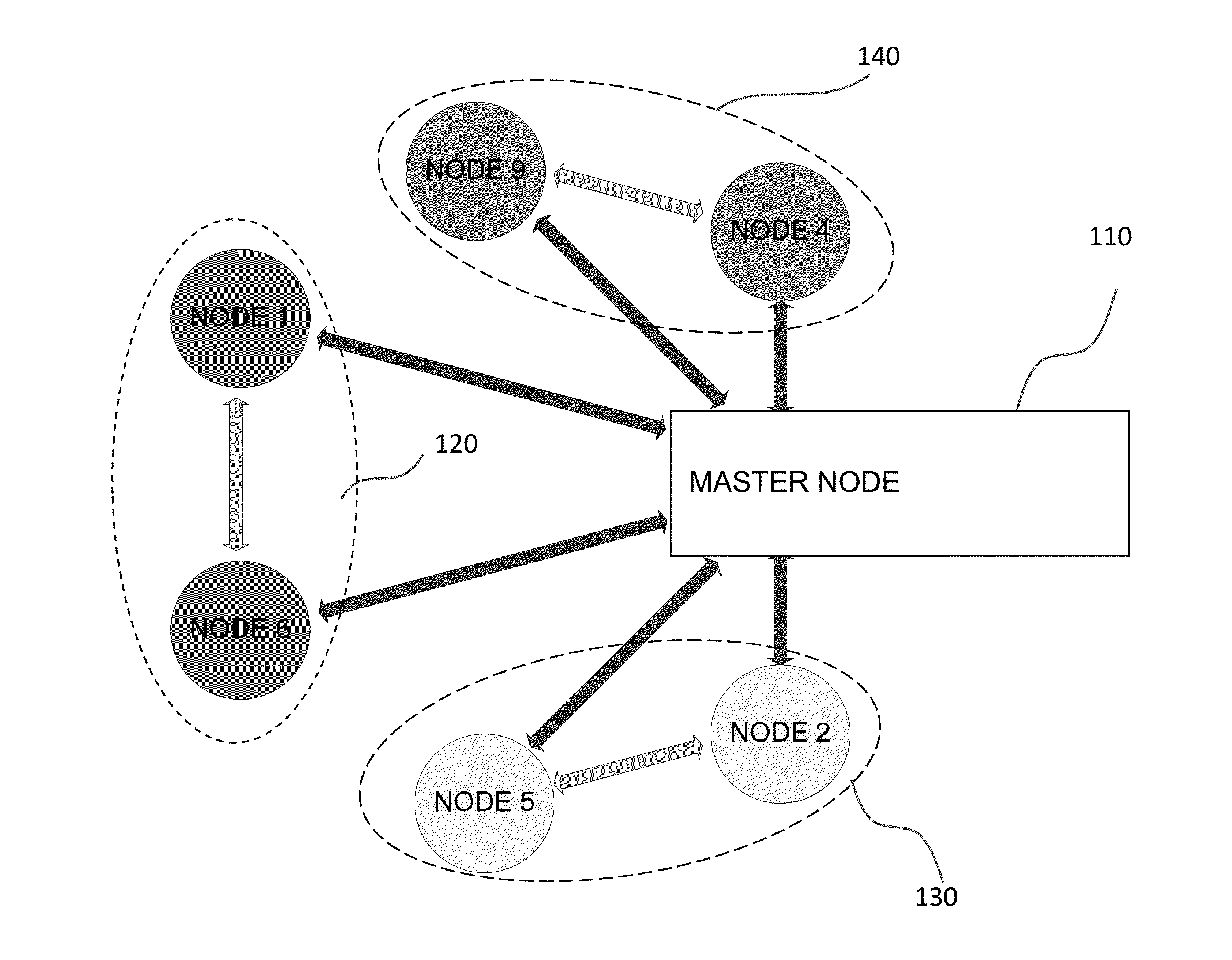
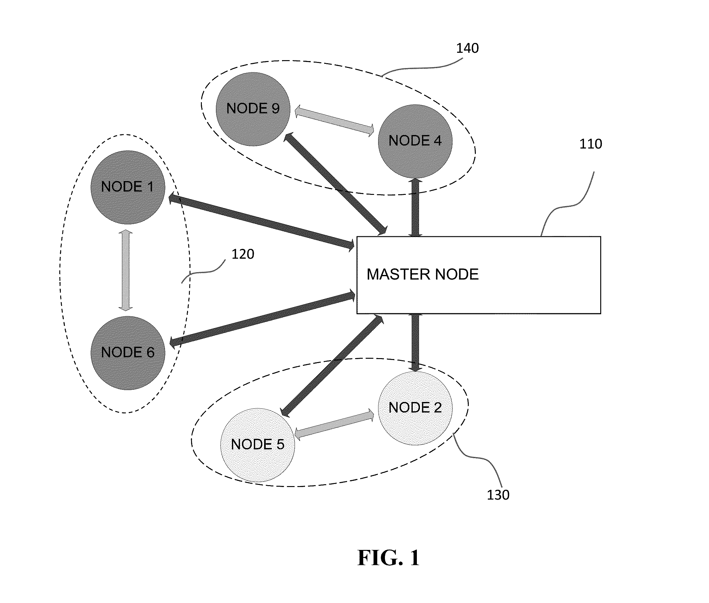
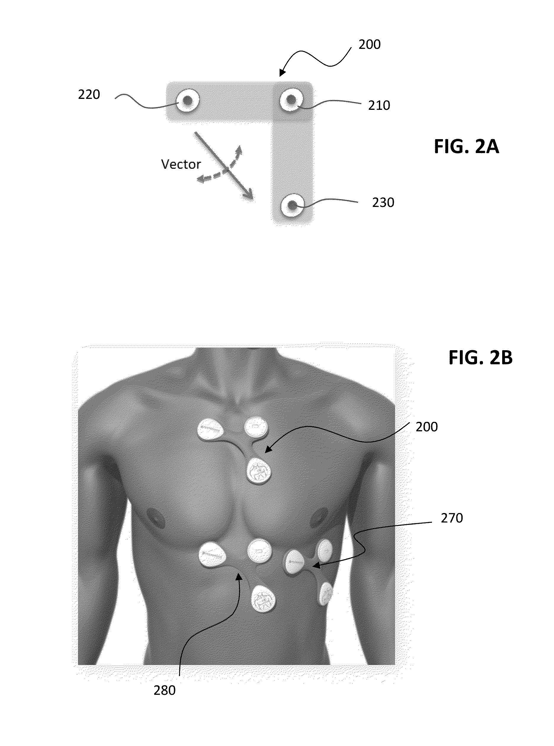
[0031]Certain embodiments of the present invention will now be discussed with reference to the aforementioned figures. In one embodiment, the present invention provides a system for managing healthcare for a subject (which used interchangeably herein with a “patient”). The system includes a plurality of wireless sensors suitable for attachment to the skin of a subject or implantable in the body of the subject. The plurality of wireless sensors can form a network. The type of network may utilize a routing topology include: star, mesh, pseudo-mesh network, or any other routing topology. Each of the sensors can include a sensing component configured to detect a signal corresponding to at least one physiological condition of the subject, and a communication component configured to wirelessly transmit the detected signal to either another wireless sensor or an external monitoring unit. The communication component of selected sensors can also be configured to receive and / or relay signals ...


PUM


Abstract

A system for detecting an electrocardiogram (ECG) signal of a subject includes a substrate that is placed on and adheres to the skin over the sternum of the subject. First, second and third electrodes are disposed on the substrate, each of which has an end for contacting a respective area of skin. Directional positioning from the second electrode to the first electrode is substantially perpendicular to directional positioning from the third electrode to the first electrode. A circuit on the first substrate is connected to the electrodes and generates a first ECG channel measuring a difference in electric signals between the first electrode and the second electrode, and a second ECG channel measuring a difference in electric signals between the first electrode and the third electrode. A communication component on the substrate wirelessly transmits ECG information from the circuit to an external device.

Description

CROSS-REFERENCE TO RELATED APPLICATIONS[0001]This application is a continuation of U.S. application Ser. No. 14 / 216,174, filed Mar. 17, 2014, which claims priority to U.S. provisional application No. 61 / 787,772, filed on Mar. 15, 2013, and U.S. provisional application No. 61 / 924,986, filed Jan. 8, 2014, the disclosure of each of which is incorporated herein by reference in its entirety.FIELD OF THE INVENTION[0002]The present invention relates to one or more wireless sensors, and a network of wireless sensors, for monitoring, in real time (or quasi real time), a patient's vital signs, such as various hemodynamic parameters of the patient. In addition, the present invention relates to using wireless surface-attached sensors with implantable heart monitoring devices for providing improved diagnosis, monitoring, and treatment of medical conditions. Further, the present invention relates to integration of such wireless sensors with an electronic medical record storage and management syst...

Claims


Application Information

Patent Timeline
Patent Type & Authority Applications(United States)
IPC IPC(8): A61B5/0408A61N1/39A61N1/365A61B5/00A61B5/04A61B5/296A61B5/352A61B5/361A61B5/363
CPCA61B5/04085A61B5/0006A61B5/6823A61N1/3987A61B5/04011A61N1/365A61N1/3956A61B5/6832A61B5/746A61B5/4848A61B2560/0412A61B2562/04A61B2562/164G16H50/20A61B5/341A61B5/327A61B5/282A61B5/361A61B5/363A61B5/352A61B5/349A61N1/36585
Inventor ACQUISTA, ANGELO JOSEPHKOMETZ, AVIMA, LEUNG-HANGSHAMBROOM, JOHN
Owner PEERBRIDGE HEALTH
Why Eureka
Try Eureka