Exhaust gate

a technology of exhaust gate and valve flap, which is applied in the direction of valve housing, machine/engine, transportation and packaging, etc., can solve the problems of generating particularly low pressure loss, and achieve the effect of low leakage, favorable construction, and precise bearing of the valve flap

Active Publication Date: 2015-08-27
BORGWARNER STUTTGART GMBH
View PDF4 Cites 6 Cited by
  • Summary
  • Abstract
  • Description
  • Claims
  • Application Information

AI Technical Summary

Benefits of technology

[0012]According to a further configuration of the invention, a cylindrical outlet connection piece having an end face as the valve seat may be formed at the second outlet. The outlet connection piece can be fixed in a predefined installation position on the second outlet. In this manner, a particularly precise bearing of the valve flap against the valve seat of the second outlet can be ensured. Particularly low leakage in the closed position of the second outlet can thus be achieved.
[0013]According to a further configuration of the invention, the first valve seat and the second valve seat are arranged at an angle of less than 90° with respect to each other, or at an angle of less than 70°, or particularly at an angle of 50 to 60° with respect to each other. This ensures a particularly favorable construction in terms of flow, with low pressure loss. Moreover, a small setting angle is produced.
[0014]In another embodiment of the invention, the housing and the outlet connection piece consist of a stainless casting alloy, particularly of a stainless steel i

Problems solved by technology

Since a flow edge is omitted and as a result a larger cross sec

Method used


Image

  • Exhaust gate
  • Exhaust gate
  • Exhaust gate

Examples


Embodiment Construction

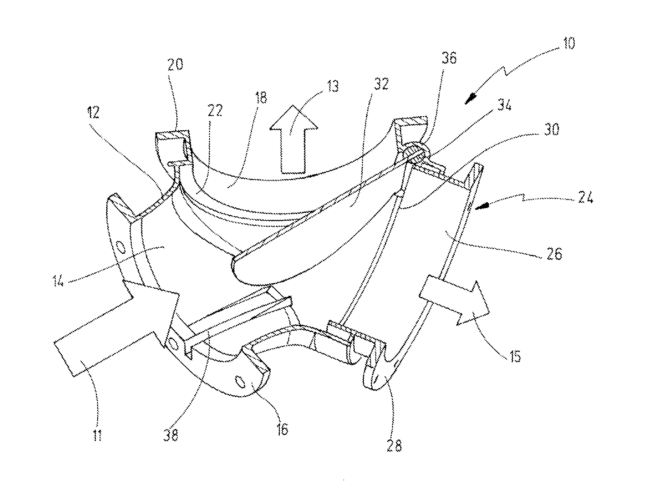
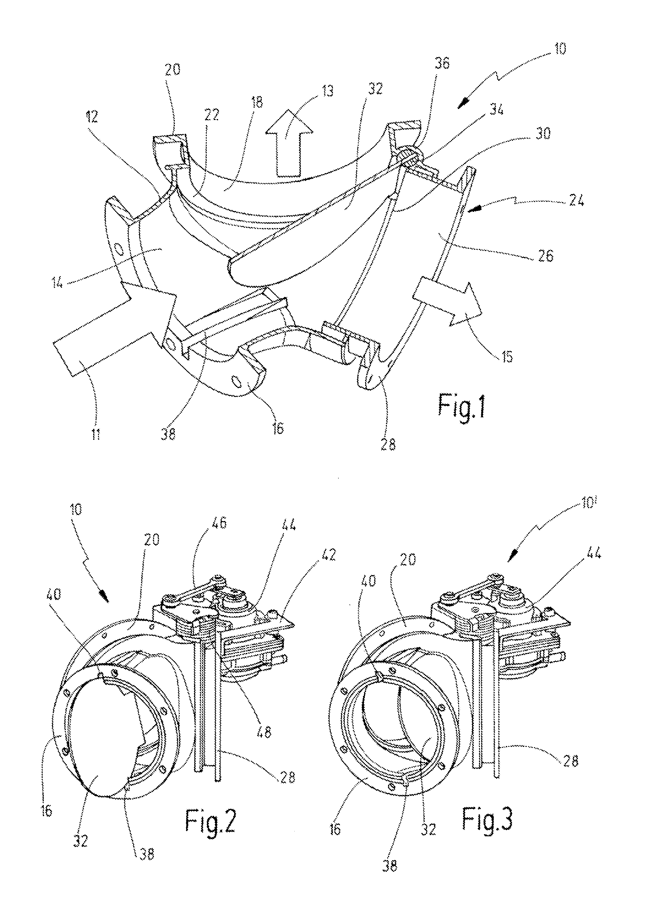
[0026]FIG. 1 shows an exhaust gate according to the invention, which taken as a whole is referred to with the number 10.

[0027]The exhaust gate 10 is provided in particular for heavy-goods vehicles and acts to deflect exhaust gases, which flow into the inlet 14 of the exhaust gate 10 in the direction of the arrow 11, between a first outlet 18 according to arrow 13 and a second outlet 24 according to arrow 15. While the first outlet 18 is typically connected to a thermal energy recovery system, for instance a heat exchanger or evaporator, the second outlet 24 is typically connected to a bypass, which leads directly to the exhaust pipe. The exhaust gas stream is deflected entirely or partially between the first outlet 18 and the second outlet 24 typically depending on a series of operating parameters, such as the exhaust gas mass flow, the exhaust gas temperature and where necessary further operating parameters.

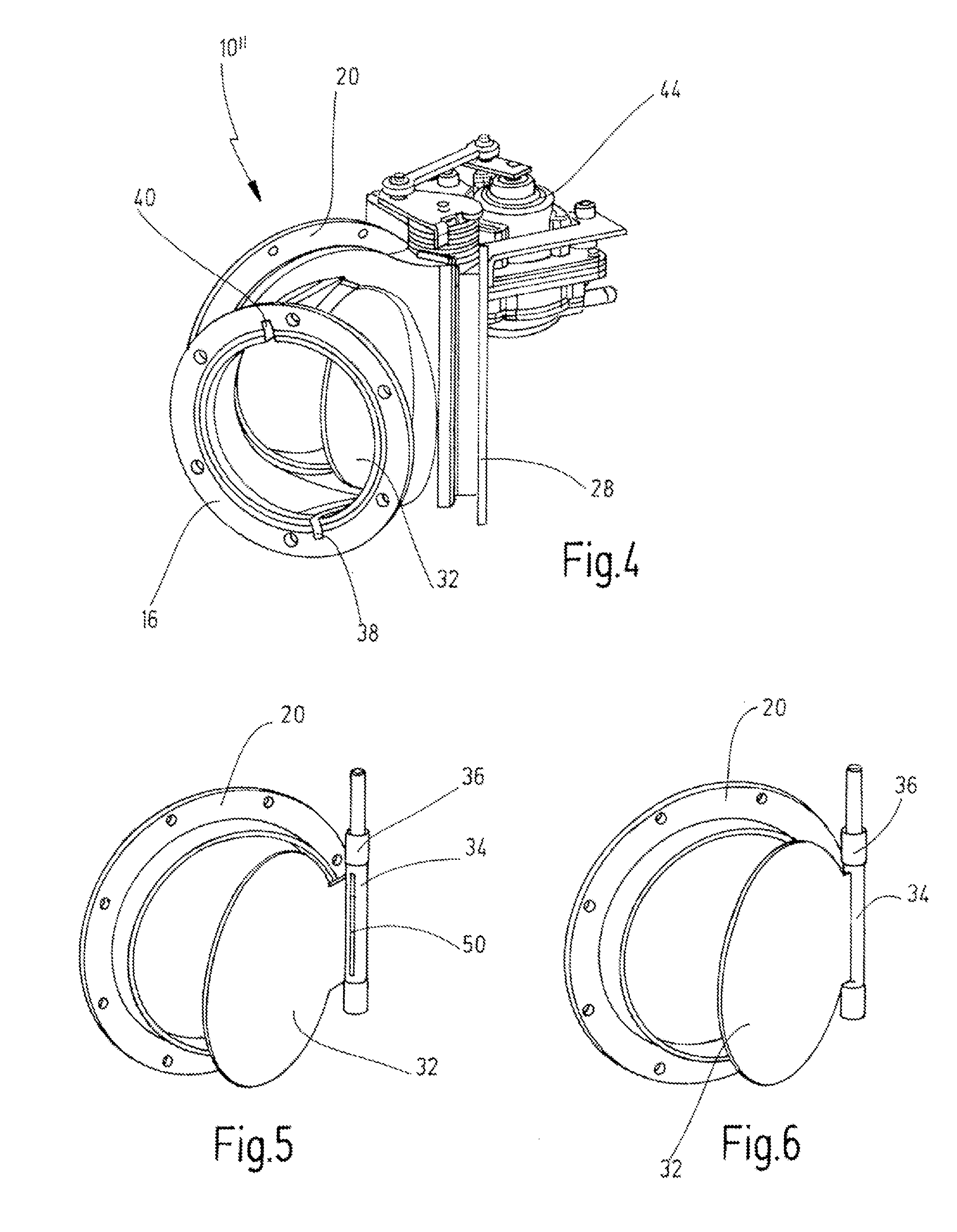
[0028]For the deflection, a flap valve is used, which has a valve flap 32 w...


PUM


Abstract

An exhaust gate, in particular for a heavy-goods vehicle, has a housing, which has an inlet and first and second outlets, on which first and second valve seats are formed, and a valve flap, which can be pivoted between the two valve seats to close the first or second outlet. The housing is formed as a cast part, which connects the inlet and at least the first outlet integrally to each other. The valve flap has a larger cross section than the inlet and the first and second valve seats.

Description

CROSS-REFERENCE TO RELATED APPLICATIONS[0001]This application claims priority to German Patent Application No. 10 2014 102 358.7, filed Feb. 24, 2014, the entire contents of which are hereby incorporated by reference.DESCRIPTIONField of the Invention[0002]The invention relates to an exhaust gate, in particular for heavy-goods vehicles, having a housing, which has an inlet and first and second outlets, on which first and second valve seats are formed, and having a valve flap, which can be pivoted between the two valve seats to close the first or second outlet.BACKGROUND OF THE INVENTION[0003]An exhaust gate of the prior art is known from DE 10 2010 010 332 A1. Said document discloses an exhaust gate in which the exhaust gas can be deflected by means of a flap valve between a first outlet, which is provided with an exhaust gas cooler, and a second outlet, which acts as a bypass. The exhaust gate mentioned above has a high pressure loss in the control range of the flap valve.[0004]Exha...

Claims


Application Information

Patent Timeline
IPC IPC(8): F16K11/052F01N13/08F01N9/00F01N13/00F01N13/16
CPCF16K11/0525F01N13/002F01N13/087F01N9/00F01N13/16F16K11/052F16K27/0227F02M26/26F02M26/70F02M26/71Y10T137/87812
Inventor ELSAESSER, MATHIASBAREIS, BERNDDOLD, ROLANDMOELLER, MARTINSTANZEL, NICOLASZUSCHLAG, AXELJUNG, MANUELSCHULZ, MARTINGAUDRY, JEAN-FRANCOISSCHEFFEL, HELMUT
Owner BORGWARNER STUTTGART GMBH
Why Eureka
Try Eureka