Enhanced stitching by overlap dose and feature reduction

a technology of overlap dose and feature reduction, applied in the field of methods and systems for exposing targets, can solve the problems of error and uncertainty, stage movement and exact position of the target, sub-area of the target scanned by one beam may not be perfectly aligned with the adjacent sub-area of the target scanned by another beam, etc., to achieve the effect of improving critical dimension uniformity, increasing exposure latitude, and increasing exposure dos

Active Publication Date: 2015-08-27
ASML NETHERLANDS BV
View PDF8 Cites 13 Cited by
  • Summary
  • Abstract
  • Description
  • Claims
  • Application Information

AI Technical Summary

Benefits of technology

[0017]The invention makes use of a higher exposure dose in the overlap area to increase exposure latitude to improve critical dimension uniformity (CDu) in the overlap area. Because more than one beam is available to write in the overlap area, a higher exposure dose can be imparted in the overlap area without incurring a throughput penalty. In this way, stitching can be performed to deal with mis-alignment in the lithography system while maintaining a CDu in the overlap areas which is comparable or better than the CDu in the non-overlap areas where there is no stitching.
[0018]In one aspect the invention provides a method for processing exposure data for exposing a pattern on a target using a plurality of charged particle beams, the exposure data comprising pattern data representing one or more features to be written on the target, the method comprising dividing the pattern data into a plurality of sub-sections, each of the sub-sections comprising pattern data describing a part of the pattern to be written in a corresponding sub-area of the target, wherein the pattern data comprises overlap pattern data describing a part of the pattern to be written in a corresponding overlap area of the target where adjacent sub-areas overlap, and processing the overlap pattern data to reduce a size of one or more features described by the overlap pattern data. The processing reduces the size of the features described by the overlap pattern data with respect to the size of the features described by non-overlap pattern data, i.e. pattern data not part of the overlap pattern data.
[0033]In this way the exposure dose may decrease (fade out) as a beam scans across the overlap area towards the edge of a sub-area, and the exposure dose of a second beam may increase (fade in) as it scans across the overlap area starting from the edge of a sub-area. The variation in the dose values of the first and second overlap dose data may be a linear variation or a sinusoidal variation or some other variation in dependence on corresponding writing position of the dose values. Not all of the dose values need to be reduced in the overlap area, e.g. a portion of the dose values in the overlap area near to a non-overlap area may retain their previous values.

Problems solved by technology

The lithography system which generates the beams inevitably suffers from various errors and uncertainties arising during its manufacture and operation, resulting in errors and uncertainties in the exact position of each beam scanning the target relative to other beams scanning the target.
The target is usually mounted on a stage which moves during the exposure, and there are also errors and uncertainties in the stage movement and in the exact position of the target in the lithography system.
As a result, a sub-area of the target scanned by one beam may not be perfectly aligned with an adjacent sub-area of the target scanned by another beam.
Although these techniques can reduce the impact of imperfect alignment between neighboring sub-areas, they require complex calculation in dependence on the topology of the features to be exposed and may still result in a significantly higher variation in critical dimension (CD) in the stitching region than in other regions of the target.
In a different electron beam lithography technique, known as cell (or character) projection electron beam lithography, stitching defects may occur between neighbouring shot areas.
This however reduces the throughput of such systems.
These disclosures, however, do not offer any solution to reducing the stitching errors in multiple charged beam direct write lithography described above.

Method used


Image

  • Enhanced stitching by overlap dose and feature reduction
  • Enhanced stitching by overlap dose and feature reduction
  • Enhanced stitching by overlap dose and feature reduction

Examples


Embodiment Construction

[0066]The following is a description of various embodiments of the invention, given by way of example only and with reference to the drawings. Unless noted otherwise, the drawings are not drawn to scale.

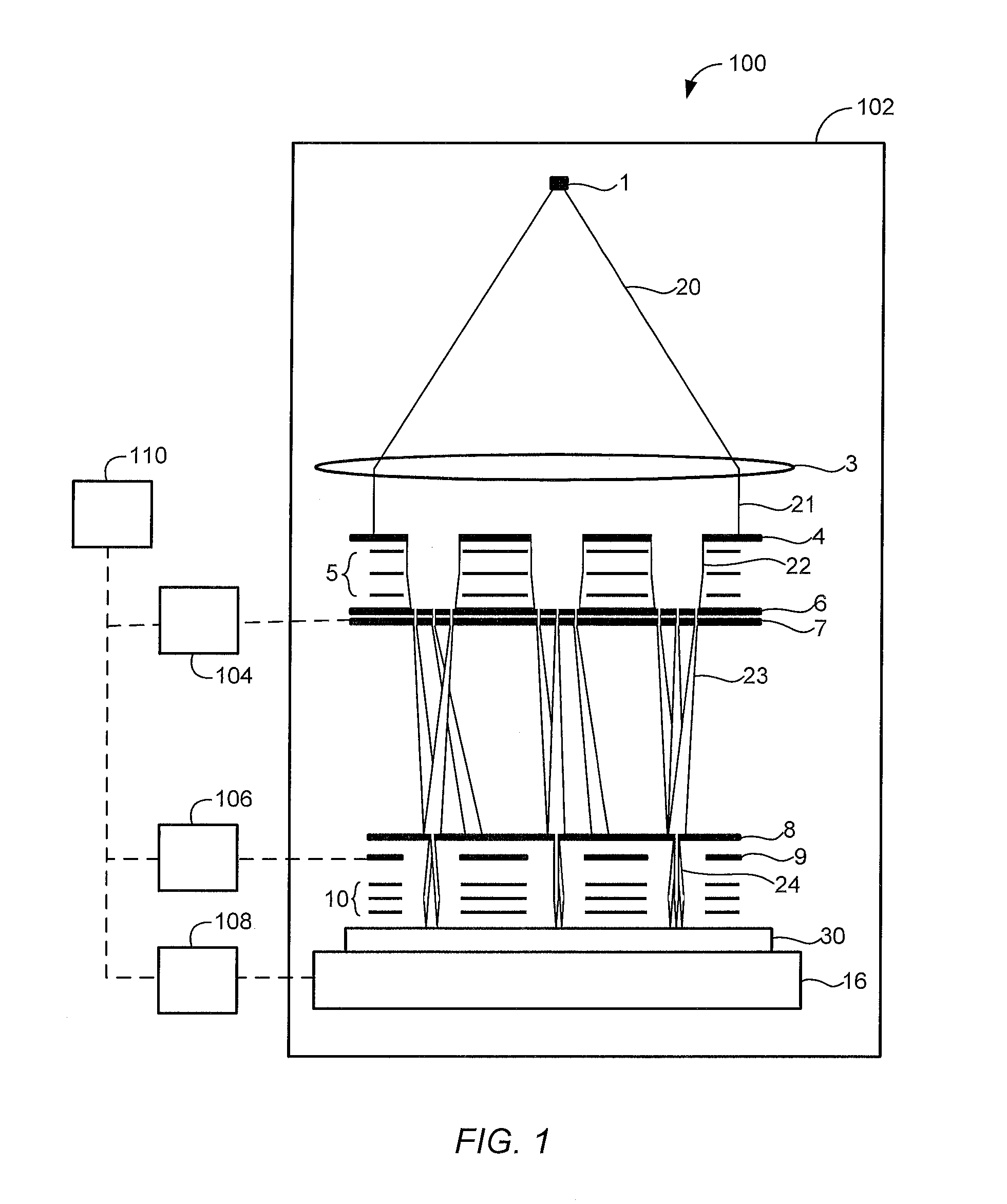
[0067]FIG. 1 shows a simplified schematic drawing of an embodiment of a charged particle multi-beamlet lithography system. The embodiment shown is based upon an electron beam optical system having no common cross-over of all the electron beams, such as described for example in U.S. Pat. Nos. 6,897,458; 6,958,804; 7,019,908; 7,084,414; 7,129,502; 7,709,815; and 7,842,936, which are all assigned to the owner of the present invention and are all hereby incorporated by reference in their entirety. The embodiment shown forms a plurality of beamlets from a plurality of sub-beams.

[0068]An electron source 1 produces a homogeneous expanding electron beam 20 which passes a collimator system 3 to produce a collimated electron beam 21 and then impinges on sub-beam aperture array 4. The aperture ...


PUM


Abstract

A method for processing exposure data (40) for exposing a pattern on a target (30) using a plurality of charged particle beams (24), the exposure data comprising pattern data (42) representing one or more features (60) to be written on the target (30) and exposure dose data (52) describing exposure dose of the charged particle beams. The method comprises setting one or more dose values of the exposure dose data (52) such that a sum of dose values corresponding to a position in an overlap area (36) of the target exceeds a maximum dose value for the non-overlap areas (38) of the target where adjacent sub-areas (34) do not overlap, and dividing the pattern data (42) into a plurality of sub-sections (44), each of the sub-sections comprising pattern data describing a part of the pattern to be written in a corresponding sub-area (34) of the target (30), wherein the pattern data (42) comprises overlap pattern data (46) describing a part of the pattern to be written in a corresponding overlap area (36) of the target where adjacent sub-areas (34) overlap, and processing the overlap pattern data (46) to reduce a size of one or more features described by the overlap pattern data.

Description

BACKGROUND OF THE INVENTION[0001]1. Field of the Invention[0002]The present invention relates to methods and systems for exposing a target using charged particles, and methods and systems for processing exposure data for use in charged particle lithography, and in particular to methods and systems for performing stitching during exposure of a target.[0003]2. Description of the Related Art[0004]In a multi-beam lithography system, multiple beams are used to expose a target, such as a silicon wafer coated with resist. Charged particle beams, such as electron beams, are usually used. The multiple beams are scanned across the surface of the target, each beam simultaneously writing a portion of the pattern onto a portion of the target. To provide the required precision at a satisfactory throughput, a very large number of beams may be used, e.g. tens or hundreds of thousands, or even millions of beams. An example of such a system is described in M. J. Wieland et al, “Throughput enhancement...

Claims


Application Information

Patent Timeline
Patent Type & Authority Applications(United States)
IPC IPC(8): G06F17/50H01L21/263
CPCH01L21/263G06F17/5081G03F7/70475H01J37/3177H01J37/3026H01J2237/31769G03B27/42G03F1/78G03F7/2059H01J37/317G06F30/398
Inventor WIELAND, MARCO JAN-JACO
Owner ASML NETHERLANDS BV
Why Eureka
Try Eureka