Low cost wireless (resistive) sensor based on impedance coupling/modulation using mrc

a wireless resistive sensor and impedance coupling technology, applied in the direction of instruments, capacitor propulsion, transportation and packaging, etc., can solve the problems of wiring in the vehicle, especially many wires, and the electrical conductor of the wires, such as copper, to be easily damaged, and achieve the effect of reducing the risk of damage to the wiring in the vehicl

Active Publication Date: 2015-08-27
GM GLOBAL TECH OPERATIONS LLC
View PDF5 Cites 13 Cited by
  • Summary
  • Abstract
  • Description
  • Claims
  • Application Information

AI Technical Summary

Problems solved by technology

However, there are a number of disadvantages with providing wires in a vehicle, especially many wires.
For example, the electrical conductor of the wires, such as copper, has significant weight.
Further, wiring in a vehicle is susceptible to damage, which increases the warranty cost of the vehicle.
Also, requiring wiring throughout the vehicle reduces the flexibility in design and manufacturing of the vehicle.
Further, at least some of the wiring in a vehicle often requires periodic maintenance.
Also, wiring adds significant expense and cost.
Further, during manufacture of the vehicle, assembly of cable harnesses often causes problems as a result of breaking or bending of connector pins.
However, the transmission of wireless signals also suffers from a number of disadvantages including interference with signals from other vehicles, potential interference with signals from consumer devices brought into the vehicle, unnecessary radiation inside the passenger compartment of the vehicle, and fading issues, which result in loss of signal, requiring larger transmitted power and large power consumption.

Method used


Image

  • Low cost wireless (resistive) sensor based on impedance coupling/modulation using mrc
  • Low cost wireless (resistive) sensor based on impedance coupling/modulation using mrc
  • Low cost wireless (resistive) sensor based on impedance coupling/modulation using mrc

Examples


Embodiment Construction

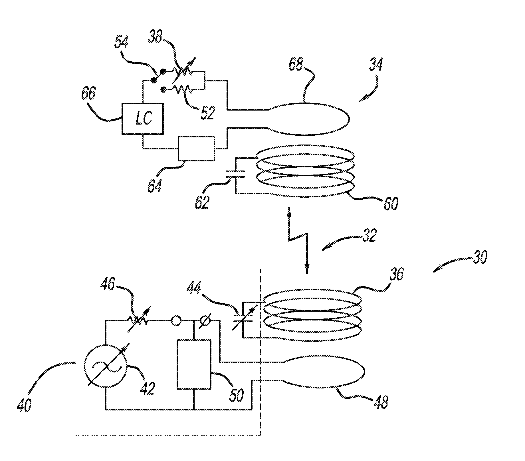
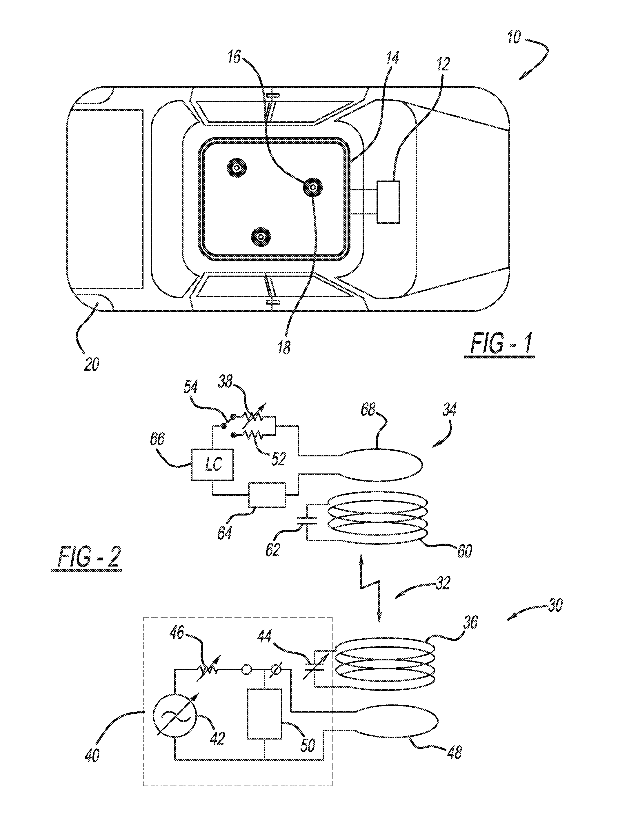
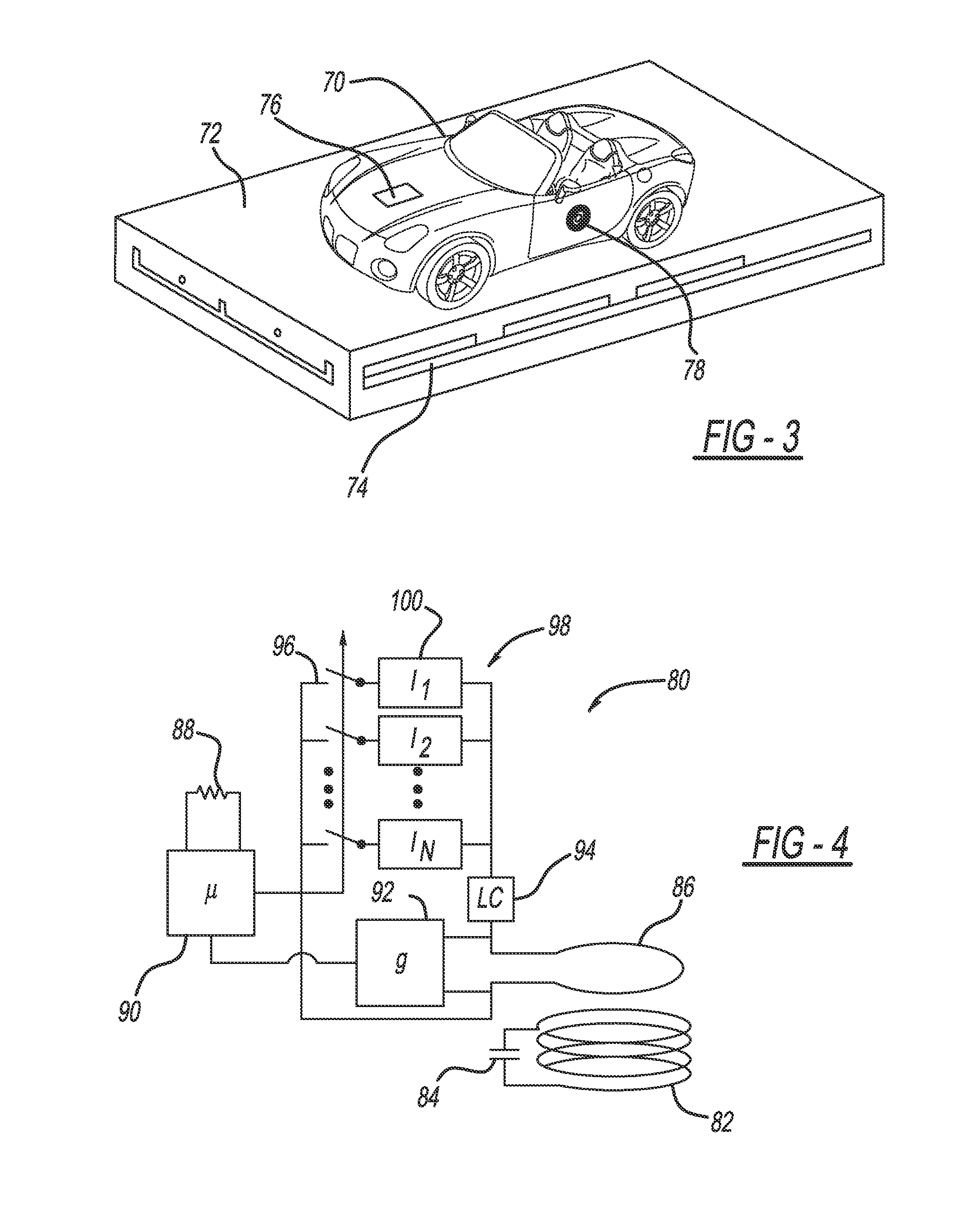
[0013]The following discussion of the embodiments of the invention directed to a magnetic resonance coupling system for transmitting data signals from a sensor on a vehicle through magnetic resonance coupling (MRC) is merely exemplary in nature, and is in no way intended to limit the invention or its applications or uses. For example, as discussed, the magnetic resonance coupling system has particular application for transmitting data signals from a sensor on a vehicle. However, as will be appreciated by those skilled in the art, the magnetic resonance coupling system may have other applications on other mobile platforms, such as on trains, machines, tractors, boats, recreation vehicles, etc.

[0014]The present invention proposes a system and method for providing wireless power and data communications through magnetic resonance coupling (MRC) for various peripheral devices, such as switches, actuators, sensors, etc., on a vehicle. As is well understood by those skilled in the art, MRC...


PUM

PropertyMeasurementUnit
magnetic fieldaaaaaaaaaa
resonant frequencyaaaaaaaaaa
magneticaaaaaaaaaa

Abstract

A system for transmitting data signals from a sensor on a vehicle through magnetic resonance coupling (MRC). The system includes a control circuit having a base coil, a variable current source, a variable capacitor and a control load, where the variable current source and the capacitor are tuned to provide a predetermined AC current to the base coil so as to generate an oscillating magnetic field at a predetermined frequency. The system also includes a receiver circuit associated with the sensor, where the receiver circuit includes a receiver coil, a tuning capacitor and a variable resistive load. The receiver coil is tuned and magnetically coupled to the base coil at the predetermined frequency. A change in the variable resistive load in the receiver circuit in response to a sensor measurement causes a change in the voltage across the control load that gives an indication of the sensor measurement.

Description

CROSS-REFERENCE TO RELATED APPLICATIONS[0001]This application claims the benefit of the priority date of U.S. Provisional Patent Application Ser. No. 61 / 945,730, titled, Low Cost Wireless (Resistive) Sensor Based on Impedance Coupling / Modulation Using MRC, filed Feb. 27, 2014.BACKGROUND OF THE INVENTION[0002]1. Field of the Invention[0003]This invention relates generally to a system and method for transmitting data signals from a sensor through magnetic resonance coupling (MRC) and, more particularly, to a system and method for transmitting data signals from a sensor on a vehicle through MRC, where a change in a variable complex impedance load in a receiver circuit associated with the sensor causes a change in the magnetic coupling between a receiver coil in the receiver circuit and a base coil in a control circuit that changes a control load in the control circuit.[0004]2. Discussion of the Related Art[0005]Modern vehicles employ many sensors, actuators, controllers, sub-systems, b...

Claims


Application Information

Patent Timeline
Patent Type & Authority Applications(United States)
IPC IPC(8): H01F38/14G01R35/00B60L11/18G01R27/02
CPCH01F38/14B60L11/182G01R35/005G01R27/02B60L2210/30B60L2210/40B60L2240/527B60L2240/545B60L2240/547B60L2270/147B60L50/40B60L53/122Y02T10/70Y02T10/7072Y02T10/72Y02T90/14Y02T90/12
Inventor LAIFENFELD, MOSHE
Owner GM GLOBAL TECH OPERATIONS LLC
Why Eureka
Try Eureka