Focus ring

Active Publication Date: 2015-08-27
COORSTEK INC
View PDF6 Cites 8 Cited by
  • Summary
  • Abstract
  • Description
  • Claims
  • Application Information

AI Technical Summary

Benefits of technology

The technical effect of this patent text is to provide a focus ring for a plasma processing apparatus that is formed without using adhesive and can prevent abnormal electric discharge while creating a uniform plasma environment in the circumferential direction.

Problems solved by technology

It is difficult to manufacture the ingot having the greater outer diameter than the outer diameter of the substrate to be processed that has a maximum diameter.
In addition, since the focus ring is manufactured by cutting the disk-shaped member out of the ingot and hollowing out the disk-shaped member to form a ring shape, there is a problem of material waste that causes increase in manufacturing costs.
If such a silicon ring is used as a focus ring in the plasma processing apparatus, gas emission occurs due to degradation of the adhesive, hence there arises a problem of occurrence of abnormal electric discharge (arcing).
Thus, if using this silicon ring as a focus ring, there arises problems of poor thermal uniformity and non-uniformity in a plasma environment in the circumferential direction within the plasma processing apparatus.
These problems cause difficulty in performing uniform plasma processing on the substrate.

Method used


Image

  • Focus ring
  • Focus ring
  • Focus ring

Examples


embodiment

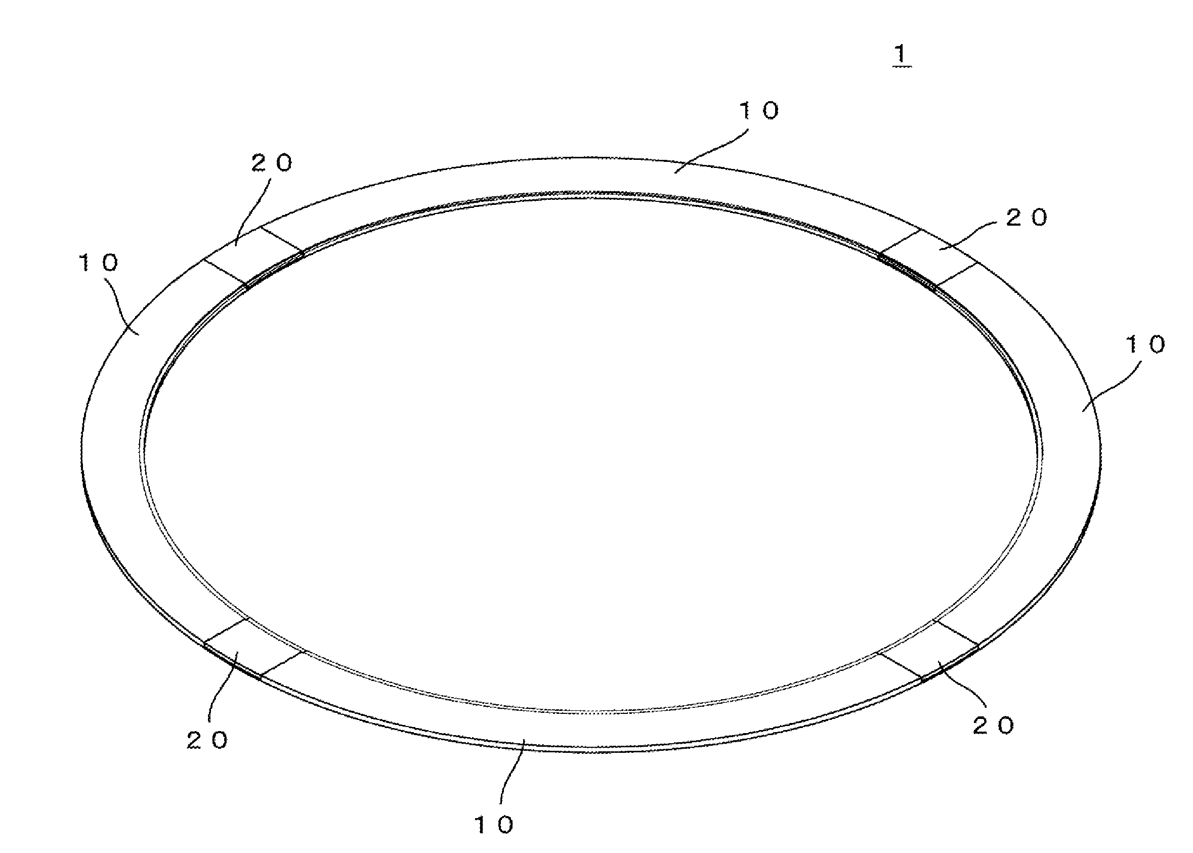
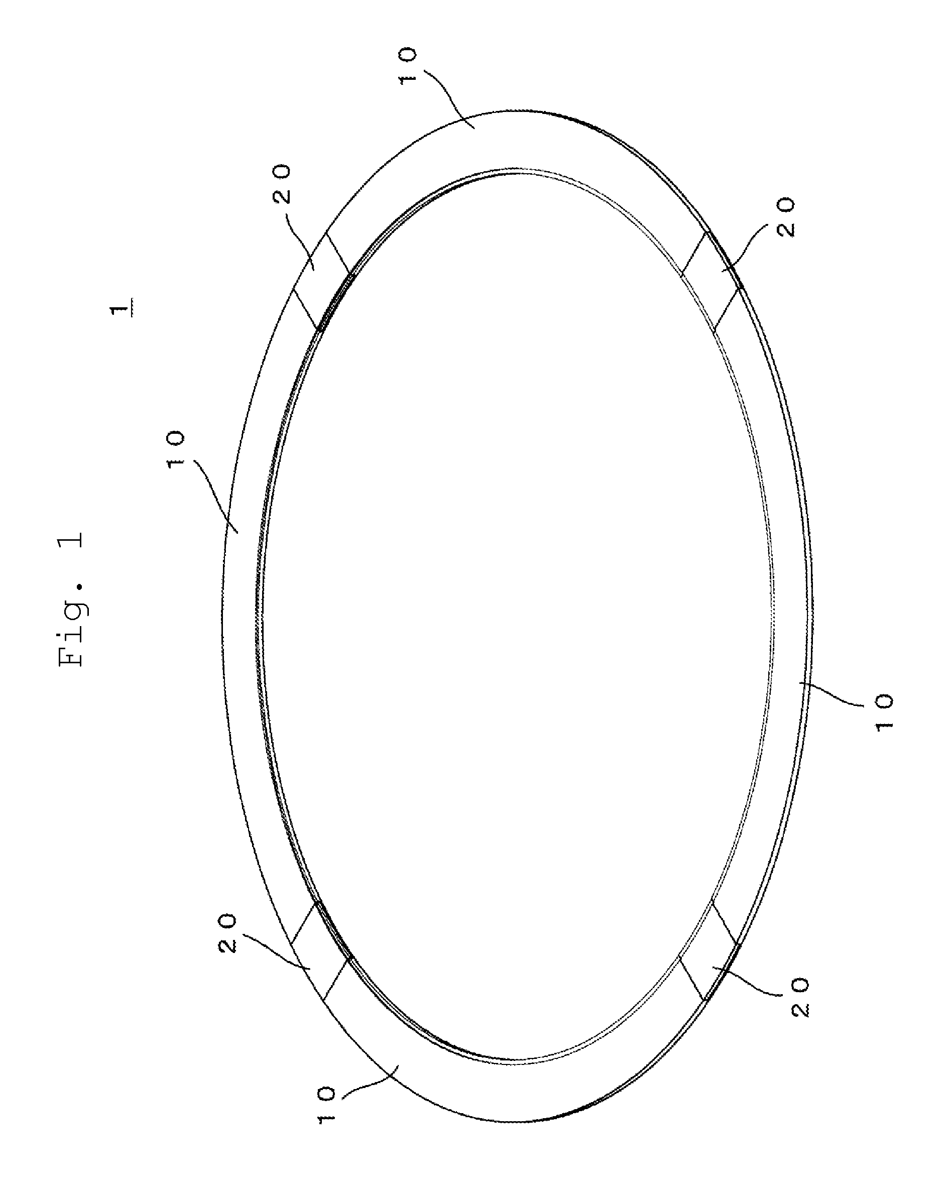
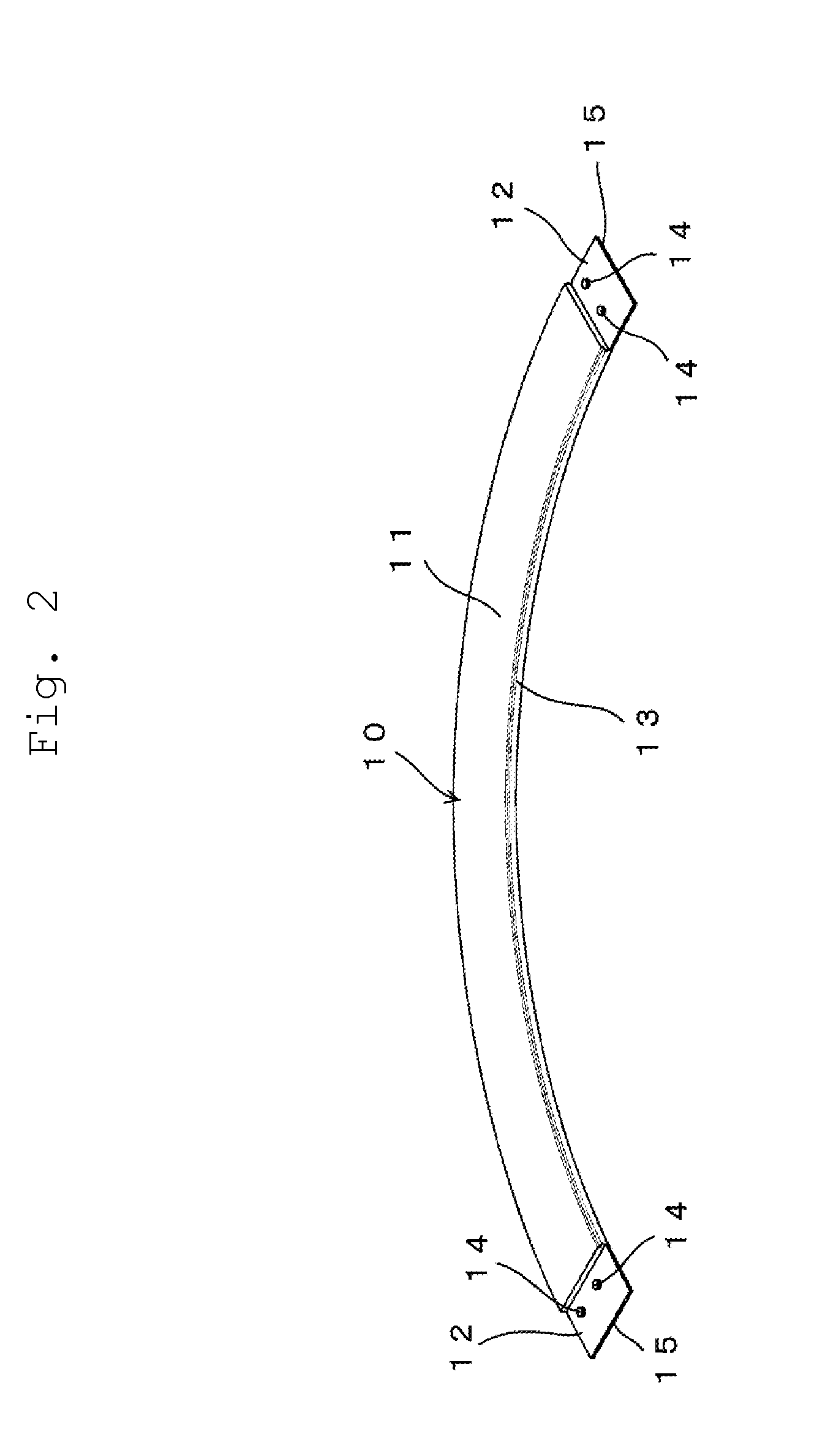
[0105]FIGS. 5 to 7 show specific shapes of the focus ring, and the arc-shaped member and the connecting member that form the focus ring.

[0106]In FIG. 5, (a) shows a plan view of the focus ring, (b) shows a front view of the focus ring, (c) shows a left-side view of the focus ring, (d) shows a right-side view of the focus ring, (e) shows a rear view of the focus ring, (f) shows a bottom view of the focus ring, and (g) shows an enlarged view of a portion indicated by the dash-dot line in FIG. 5 (d).

[0107]In FIG. 6, (a) shows a plan view of the arc-shaped member, (b) shows a front view of the arc-shaped member, (c) shows a left-side view of the arc-shaped member, (d) shows a right-side view of the arc-shaped member, (e) shows a rear view of the arc-shaped member and (f) shows a bottom view of the arc-shaped member.

[0108]In FIG. 7, (a) shows a plan view of the connecting member, (b) shows a front view of the connecting member, (c) shows a left-side view of the connecting member, (d) sho...


PUM

PropertyMeasurementUnit
Lengthaaaaaaaaaa
Lengthaaaaaaaaaa
Fractionaaaaaaaaaa

Abstract

There is provided a focus ring formed without an adhesive that can suppress abnormal electric discharge and obtain uniform plasma environment in a circumferential direction in a plasma processing apparatus. The focus ring includes a plurality of arc-shaped members and a plurality of connecting members connecting the plurality of the arc-shaped members to form a ring shape without an adhesive, and is formed such that a thickness between an upper surface of the connecting member and a bottom surface of a concave fitting portion of the connecting member is greater than a thickness between an upper surface of the arc-shaped member and a bottom surface of a second depression of the arc-shaped member.

Description

BACKGROUND OF THE INVENTION[0001]1. Field of the Invention[0002]The present invention relates to a focus ring, and in particular to a focus ring for placing a substrate to be processed thereon at an inner periphery portion of the focus ring, and that is disposed at an outer side of the substrate to be processed in a plasma processing apparatus.[0003]2. Description of the Related Art[0004]In a semiconductor device manufacturing process, a plasma processing apparatus such as a plasma etching apparatus and a plasma CVD apparatus is used for processing such as etching a substrate to be processed.[0005]At that time, a focus ring is disposed to surround the substrate to be processed for performing the plasma processing uniformly on the substrate.[0006]The focus ring is disposed at an outer side of the substrate to be processed, and for example, the substrate to be processed is placed at an inner periphery portion of the focus ring so as to form so-called a pseud substrate (pseud wafer) ar...

Claims


Application Information

Patent Timeline
IPC IPC(8): H01J37/32
CPCH01J37/32642H01J2237/334H01J2237/049
Inventor KUBOTA, MASAHIROSHIMA, TAKAAKI
Owner COORSTEK INC
Why Eureka
Try Eureka