Drilling method for drilling a subterranean borehole

a subterranean borehole and drilling method technology, applied in the direction of borehole/well accessories, survey, sealing/packing, etc., can solve the problems of mud entering the formation, momentary reduction of bhp, formation of kicks, etc., and achieve the effect of higher level of safety

Active Publication Date: 2015-09-10
GRANT PRIDECO LP
View PDF2 Cites 8 Cited by
  • Summary
  • Abstract
  • Description
  • Claims
  • Application Information

AI Technical Summary

Benefits of technology

[0061]The first riser chamber may be provided with an outlet situated below the sealing device and connected to a fluid return line, and the method further include the step of closing a return valve in the return line to prevent flow of fluid along the return line before opening the valve in the flow line.
[0062]The table below compares the inventive method (‘Zero ECD’) to the current drilling methods in use, with their corresponding levels of safety for enhancing well and riser pressure control. The table illustrates that the inventive method yields a higher level of safety when compared to current drilling methods.

Problems solved by technology

Under such circumstances, the pressure of mud at the bottom of the wellbore can fracture the formation, and mud can enter the formation.
This loss of mud causes a momentary reduction in BHP which can, in turn, lead to the formation of a kick.
Exceeding the formation fracture pressure can also lead to the mud being lost as it flows into the formation.
Depending on the magnitude of these losses there is a significant risk that the consequent decrease in the hydrostatic pressure in the well will result in a decreased height / level of mud in the wellbore with a corresponding decrease of the BHP to below the formation pressure.
This undesired condition will likely result in a formation influx.
This is because there are frictional losses over the total length of the wellbore, caused by, for example, the geometry of the drill string relative to the wellbore changing the annular clearance between them or the viscosity or density of the fluid affecting how it flows through the annulus.
However, should the system become underbalanced, for example, due to formation influx, it is known to increase the density of the mud so as to increase the BHP of the well bore; thereby reinstating the overbalanced drilling conditions when it is circulated in the wellbore.
Underbalanced drilling allows reservoir fluids to flow to the surface together with the mud / drilling fluid during drilling and tripping.
Running managed pressure drilling or underbalanced drilling offshore is more difficult than onshore drilling and the degree of difficulty increases when drilling deeper under the sea.
Therefore the increased hydrostatic pressures generated in the well bore and associated frictional losses substantially increase the ECD of the drilling mud.
These increases in ECD can often exceed the formation fracture pressure, at such depths.
Furthermore, formation fracture pressures may be lower than seen onshore, and so conventional overbalanced conditions are undesirable due to the high risk of fracturing the formation.
Alternatively, formation pressures in these deep water well situations can be abnormally high, requiring heavier drilling mud weights to balance the well and prevent formation influx.
This situation may also cause the circulating / drilling BHP to exceed formation fracture pressures.
This results in reduced flexibility in the circulating BHP during drilling and / or connections, posing significant challenges.

Method used


Image

  • Drilling method for drilling a subterranean borehole
  • Drilling method for drilling a subterranean borehole
  • Drilling method for drilling a subterranean borehole

Examples


first embodiment

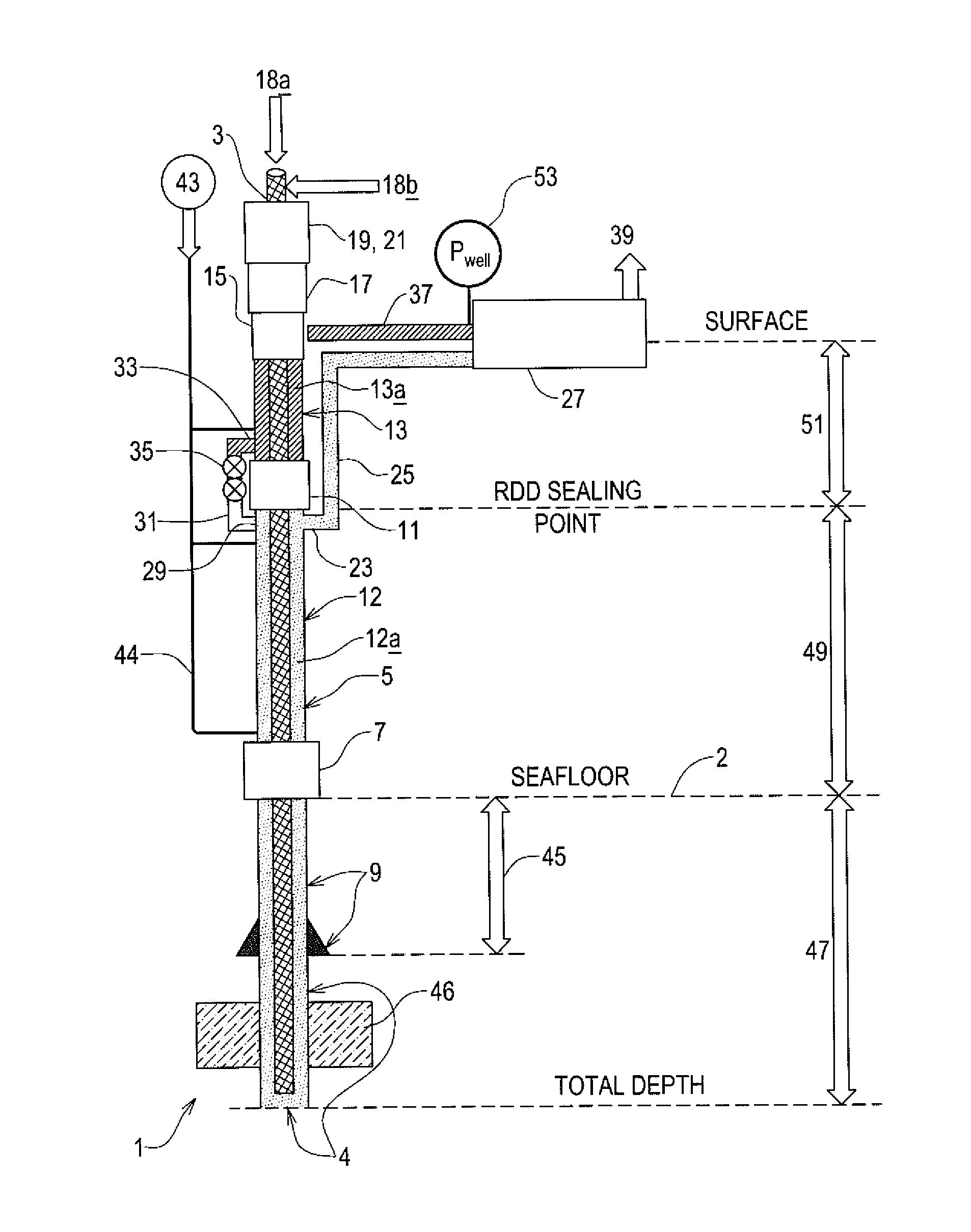
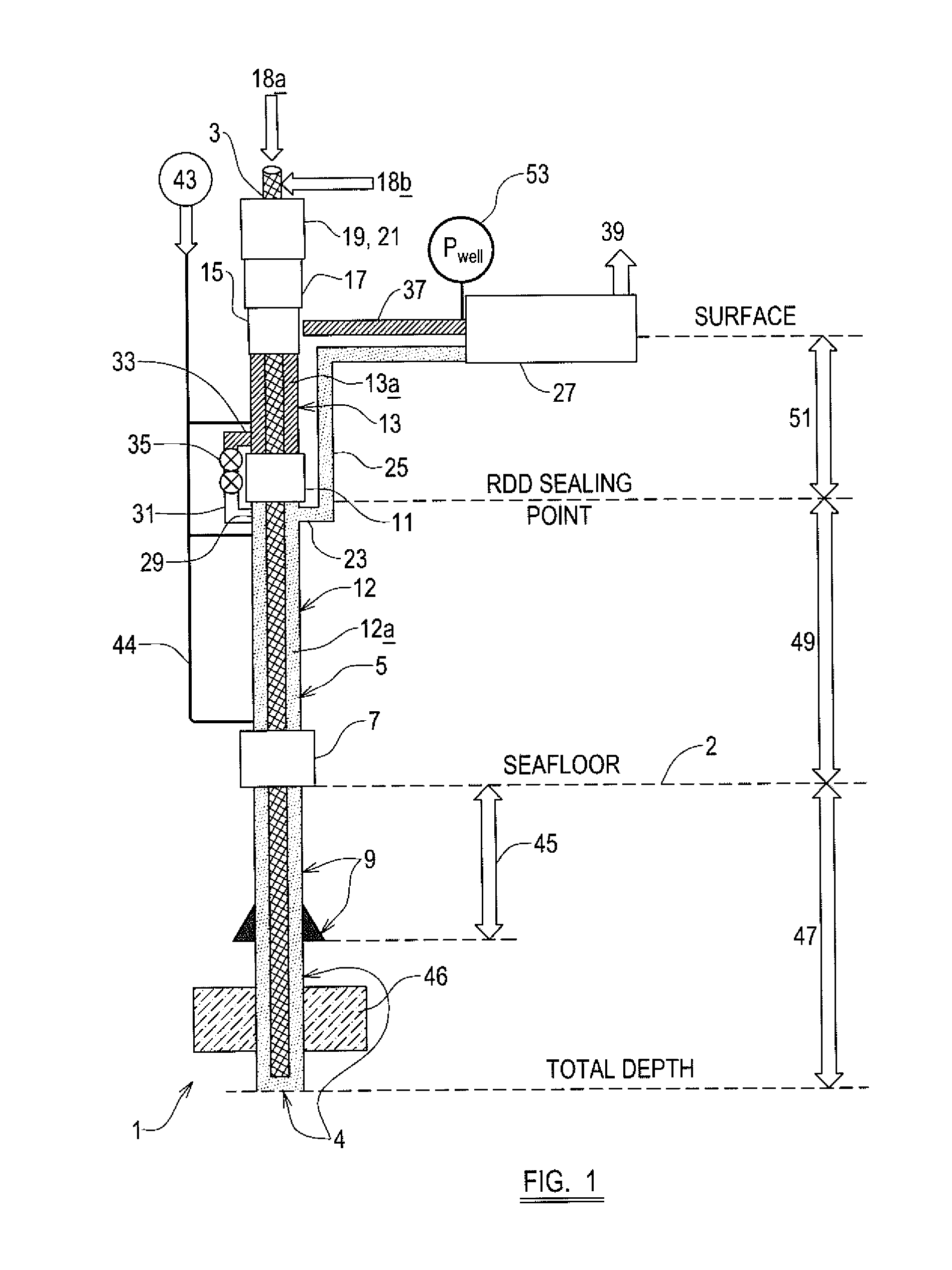
[0084]The vertical distances / depths between elements of the system will now be defined in order to illustrate (by way of example) the invention. The SSBOP 7 is located on the seabed floor 2 and is connected to the top of the well bore section 4. The wellbore 4 extends below the SSBOP and the last casing 9 is set at 5,000 ft. This length has reference numeral 45 in FIG. 1. Along this length of the wellbore 4 there is a formation 46 of hydrocarbon fluid. The open hole / drilled section extends below reference numeral 45 to a further 2,000 ft below the casing 9 resulting in a total wellbore 4 depth of 7,000 ft below the SSBOP. This length, from the seabed floor to the bottom of the open hole section has reference numeral 47. The first portion of the riser 12, which extends from the SSBOP 7 to the RDD 11, has a length of 5000 ft. This length has reference numeral 49. The second portion of the riser 13, which extends from the RDD 11 to the QCA 17, is 1,500 ft. This length has reference num...

second embodiment

[0131]All calculations are performed in the same manner as that for the second embodiment and the kill mud deployment procedure is also identical.

[0132]The second and third embodiments of the invention have other advantages over and above the use of a single mud weight of a lower static mud density, as drilling systems using a single mud density are less complex to operate in comparison to a dual-mud weight system.

[0133]Embodiments of the inventive method can be performed by modification of existing off-shore riser configurations to include a riser drilling device. Optionally, a quick closing annular preventer (QCA) and riser flow spool system may also be added to existing off-shore riser configurations. It will be appreciated that according to the embodiment employed, the QCA may be installed at, but not limited to, a position either above or below the subsea RDD that seals the first and second portions of the riser, or the QCA may not be used at all. If the QCA is not used, then t...


PUM


Abstract

A method of drilling a subterranean wellbore using a drill string including the steps of estimating or determining a reduced static density of a drilling fluid based on the equivalent circulating density of the drilling fluid in a section of the wellbore, providing a drilling fluid having substantially that reduced static density, introducing the drilling fluid having said reduced static density into the wellbore, and removing the drilling fluid from the wellbore via a return line.

Description

FIELD OF THE INVENTION[0001]The present invention relates to a method of drilling a subterranean borehole which is particularly, but not exclusively, for the purpose of extracting hydrocarbons from a subterranean oil reservoir.DESCRIPTION OF THE PRIOR ART[0002]The drilling of a wellbore is typically carried out using a steel pipe known as a drill string with a drill bit at the lowermost end. The entire drill string may be rotated using an over-ground drilling motor, or the drill bit may be rotated independently of the drill string using a fluid powered motor or motors mounted in the drill string just above the drill bit. As drilling progresses, a flow of mud is used to carry the debris created by the drilling process out of the wellbore. Mud is pumped through an inlet line down the drill string, to pass through / over / around the drill bit, and returns to the surface via an annular space between the outer wall of the drill string and the wellbore (generally referred to as the annulus)....

Claims


Application Information

Patent Timeline
Patent Type & Authority Applications(United States)
IPC IPC(8): E21B21/00E21B21/08
CPCE21B21/08E21B21/001E21B47/06E21B17/01E21B17/07E21B21/106E21B33/00E21B33/064
Inventor LEUCHTENBERG, CHRISTIANSAVAGE, PAT
Owner GRANT PRIDECO LP
Why Eureka
Try Eureka