Electronic thermometer and a control method
- Summary
- Abstract
- Description
- Claims
- Application Information
AI Technical Summary
Benefits of technology
Problems solved by technology
Method used
Image
Examples
Embodiment Construction
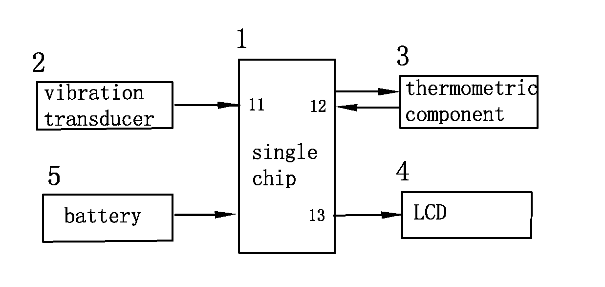
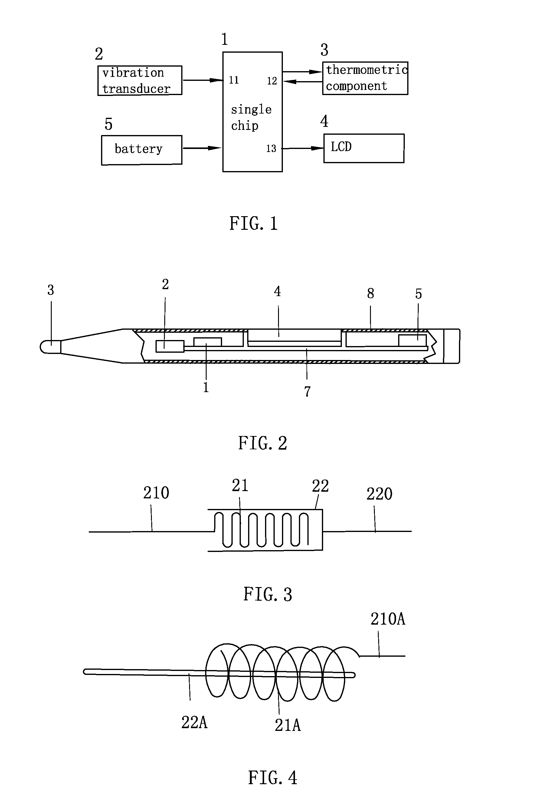
[0057]A circuit structure of an embodiment of an electronic thermometer is figured in FIG. 1. The electronic thermometer is disposed with a single chip 1, a vibration transducer 2, a thermometric component 4, an LCD 4 and a battery 5. The battery 5 supplies power to the single chip 1, the single chip 1 controls the LCD 4 and the thermometric component 3 to work. The switch type vibration transducer 2 is connected to the control input port 11 of the single chip 1 to provide vibration signal to the control input port 11 of the single chip 1. The thermometric component 3 is connected to the temperature signal input port 12 of the single chip 1, the LCD 4 is connected to the display output port 13 of the single chip 1.
[0058]Referring to FIG. 2, the thermometric component 3 is attached to the front end of a rod shaped housing 8; the single chip 1, the vibration transducer 2, the LCD 4 and the battery 5 are attached to the circuit board 7 of the housing 8, the display surface of the LCD 4...
PUM
 Abstract
Description
Claims
Application Information
 - R&D
- Intellectual Property
- Life Sciences
- Materials
- Tech Scout
- Unparalleled Data Quality
- Higher Quality Content
- 60% Fewer Hallucinations
Browse by: Latest US Patents, China's latest patents, Technical Efficacy Thesaurus, Application Domain, Technology Topic, Popular Technical Reports.
© 2025 PatSnap. All rights reserved.Legal|Privacy policy|Modern Slavery Act Transparency Statement|Sitemap|About US| Contact US: help@patsnap.com


