Bus bar, bus bar module, and method of manufacturing bus bar

a bus bar and module technology, applied in the direction of insulated conductors/cables, cables, insulating conductors, etc., can solve the problems of increasing the effective resistance within the conductor, increasing the so-called copper loss (or iron loss), and increasing the so-called iron loss, so as to reduce the loss of eddy current due to high-frequency current

Active Publication Date: 2015-09-10
KOBE STEEL LTD
View PDF7 Cites 8 Cited by
  • Summary
  • Abstract
  • Description
  • Claims
  • Application Information

AI Technical Summary

Benefits of technology

[0037]According to the bus bar, bus bar module, and manufacturing method the bus bar, according to the present invention, eddy current loss due to high-frequency current can be reduced.

Problems solved by technology

This lowers the current density flowing thorough the conductor, so the effective resistance within the conductor increases, consequently being manifested as eddy current loss.
Accordingly, forming the bus bar as a flat plate to reduce the cross-sectional area in order to suppress the high-frequency wave components increases the effective resistance for the current handling the prime power, resulting in an increase in so-called copper loss (or iron loss in a case where the material is iron).
Further, metal plates formed of material such as copper, which are plate-shaped with a certain degree of thickness, have rigidity to a certain extent, so the forming and wiring implementation thereof is not easy.
Accordingly, how to reduce overall transmission loss in bus bars which transmit current in which low-frequency waves through high-frequency waves coexist is an issue.
Moreover, twisting the entire assembled rectangular wire is equivalent to having internal inductance as in a solenoid coil, leading to unnecessary increase in inductance.

Method used


Image

  • Bus bar, bus bar module, and method of manufacturing bus bar
  • Bus bar, bus bar module, and method of manufacturing bus bar
  • Bus bar, bus bar module, and method of manufacturing bus bar

Examples


first example

[0101]A first example of the bus bar 1 according to the present embodiment was subjected to AC resistance analysis. The results thereof will be described in detail below with reference to FIG. 14.

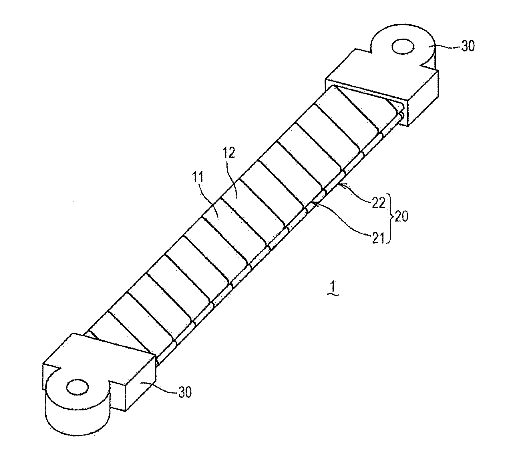
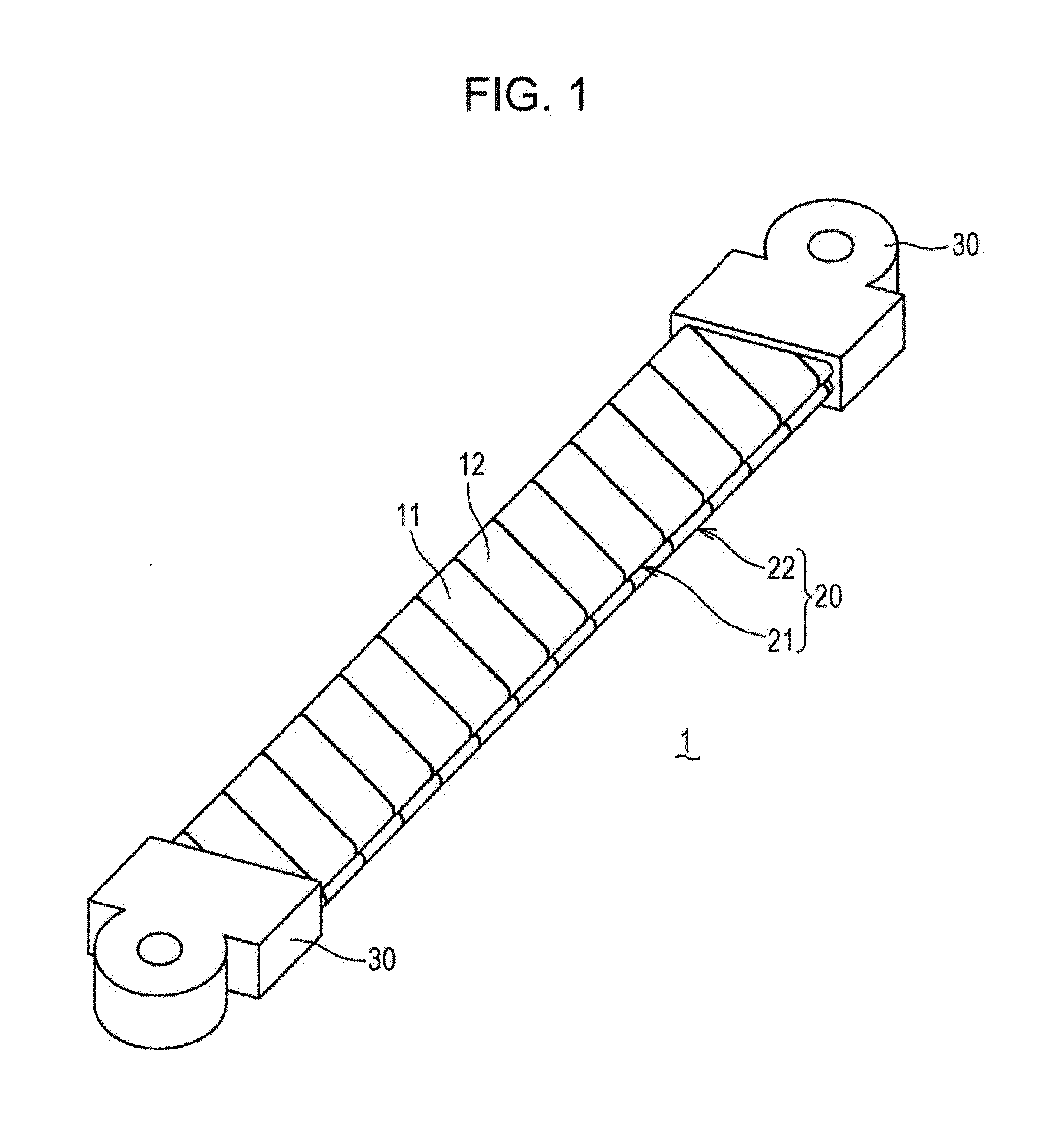
[0102]In the first example, a copper plate 0.6 mm in total thickness, which is 1 mm to several mm thinner than a commercially-used article actually used as bus bar 1, was used and frequency dependency of AC resistance was measured. In the first example, the first conductive wire 21 and the second conductive wire 22 were manufactured from two stripe conductors 11 and 12 0.15 mm t thick×19 mm W wide by the bus bar 1 manufacturing method according to the above-described embodiment. The first conductive wire 21 and the second conductive wire 22 where then brought into close contact, thereby manufacturing a laminated conductive wire 20 0.6 mm t thick×19 mm W wide to which terminal parts 30 were bonding, thus manufacturing a bus bar 1 which was used. The bus bar 1 according to the first example w...

second example

[0108]A second example of the bus bar 1 according to the present embodiment was subjected to AC resistance analysis and current density distribution analysis. The results thereof will be described in detail below with reference to FIG. 15 through FIG. 18.

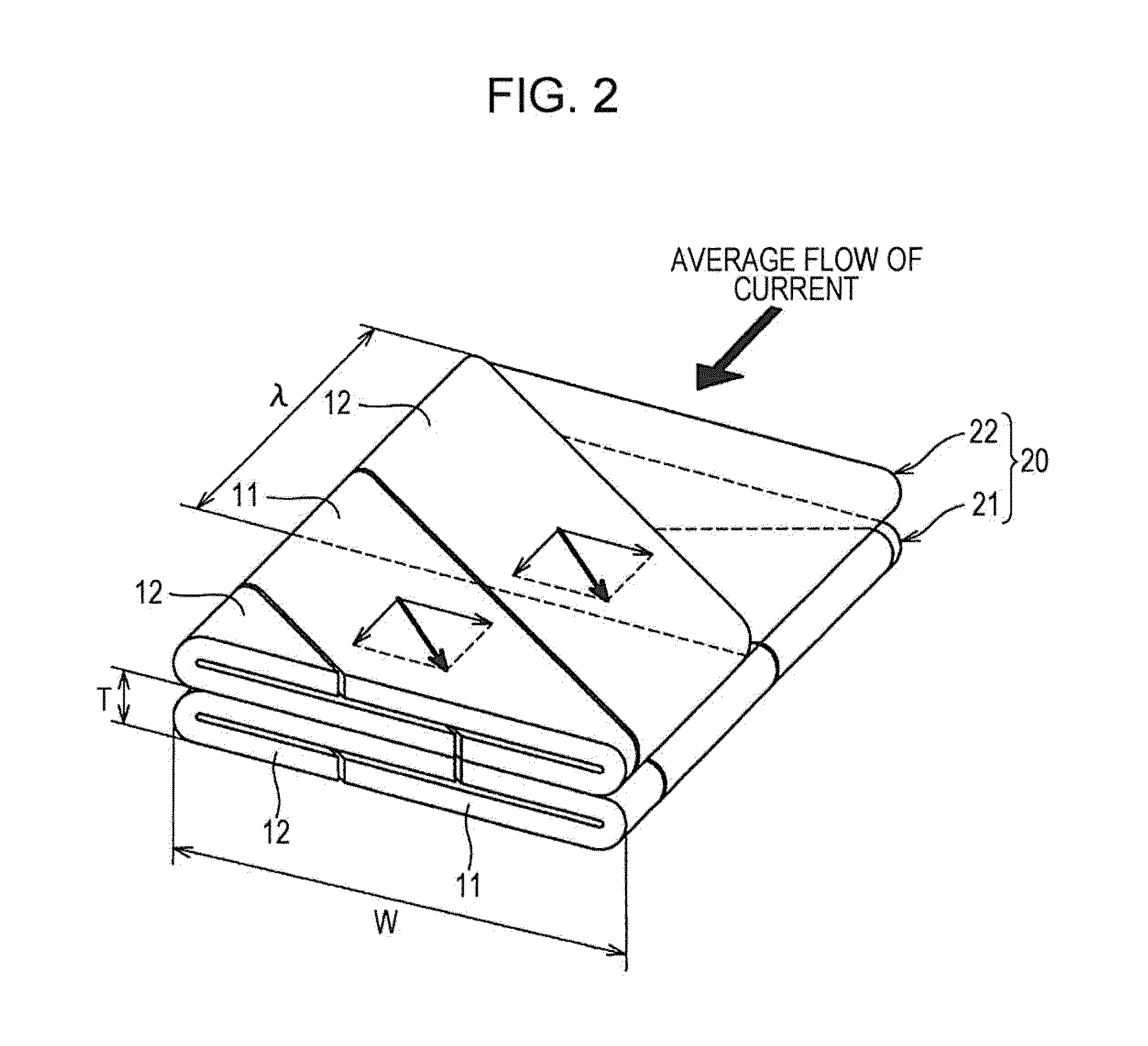
[0109]The bus bar 1 according to the second example was manufactured by the following procedures. First, stripe conductors 11 and 12 0.3 mm in thickness were wound in a spiral form with a gap of 0.4 mm therebetween. Thus, a first conductive wire 21 and second conductive wire 22 1.0 mm t thick×19 mm W wide were formed. Now, the gap between the stripe conductors 11 and 12 means a gap between the opposing surfaces on the interior of the wound stripe conductors 11 and 12, i.e., internal space in the first conductive wire 21 and the second conductive wire 22. The second conductive wire 22 was wound in spiral form in the opposite direction as to the first conductive wire 21. Next, the first conductive wire 21 and second conductive wire 22...


PUM

PropertyMeasurementUnit
aspect ratio T/Waaaaaaaaaa
total thicknessaaaaaaaaaa

Abstract

A bus bar (1) comprises: a laminated conductive wire (20) formed by arranging side by side in the longitudinal direction a first plate-shaped conductive wire (21) formed by spirally winding stripe conductors (11, 12) mutually adjacent in the width direction while bringing the opposing inner surfaces closer to each other, and a second plate-shaped conductive wire (22) formed by spirally winding the stripe conductors (11, 12) in the direction opposite the direction of the first conductive wire (21) while bringing the opposing inner surfaces closer to each other, and overlapping these wires (21, 22) so that the outer surfaces in the width direction face each other; and terminals (30) joined to the first conductive wire (21) and the second conductive wire (22) at both ends of the laminated conductive wire (20).

Description

TECHNICAL FIELD[0001]The present invention relates to a bus bar used in electric connection, a bus bar module, and a manufacturing method of the bus bar.BACKGROUND ART[0002]Bus bars and bus bar modules have conventionally been used in electric connection. For example, bus bars and bus bar modules are used in hybrid automobiles and electric automobiles where pulse width modulation (PWM: Pulse Width Modulation) driving control using particularly high-frequency current is performed.[0003]An example of the bus bar used in the system of a hybrid automobile will be described here with reference to PTL 1 and 2. In the example in PTL 1 and 2, bus bars are used for electric connection between the motor and motor inverter, and between the generator and generator inverter, and also for electric power lines within the inverter unit.[0004]Generally, high-frequency current flowing among the motor, generator, and invertor, includes high-frequency wave components due to switching that are as high a...

Claims


Application Information

Patent Timeline
Patent Type & Authority Applications(United States)
IPC IPC(8): H01B7/30H01B13/08H01B7/02
CPCH01B7/30H01B13/0891H01B7/0241H01B5/04H01B7/306H01B13/0006Y10T29/49174
Inventor OGAWA, TETSUYAFUJII, HIDEOICHIHARA, CHIKARAINOUE, KENICHI
Owner KOBE STEEL LTD
Why Eureka
Try Eureka