Body fat diagnostic apparatus

a diagnostic apparatus and body fat technology, applied in the field of body fat diagnostic apparatus, can solve problems such as theoretically difficult to apply heat to the liver

Inactive Publication Date: 2015-09-17
PUBLIC UNIVERSITY CORPORATION OSAKA CITY UNIVERSITY +1
View PDF5 Cites 7 Cited by
  • Summary
  • Abstract
  • Description
  • Claims
  • Application Information

AI Technical Summary

Benefits of technology

[0057]According to the present invention, ultrasonic waves for diagnosis and ultrasonic waves for applying heat can be emitted from the oscillators in the same probe, and therefore, safe fat measurement is carried out on a deep portion of the body, of which the depth is 4 cm or greater and on a portion inside the ribcage, where fat measurement using a change in the velocity of ultrasonic waves has been difficult according to the prior art.

Problems solved by technology

However, several problems arise as described below in the case of a biometric diagnosis using the above described dedicated probe.
However, the depth of a portion to which heat can be applied through near infrared rays from an infrared ray laser source is approximately 3 cm to 4 cm from the body surface, and it is theoretically difficult to apply heat to the liver that is located at a depth of 4 cm or greater from the body surface.

Method used


Image

  • Body fat diagnostic apparatus
  • Body fat diagnostic apparatus
  • Body fat diagnostic apparatus

Examples


first embodiment

[0066]In the following the embodiments of the present invention are described in reference to the drawings.

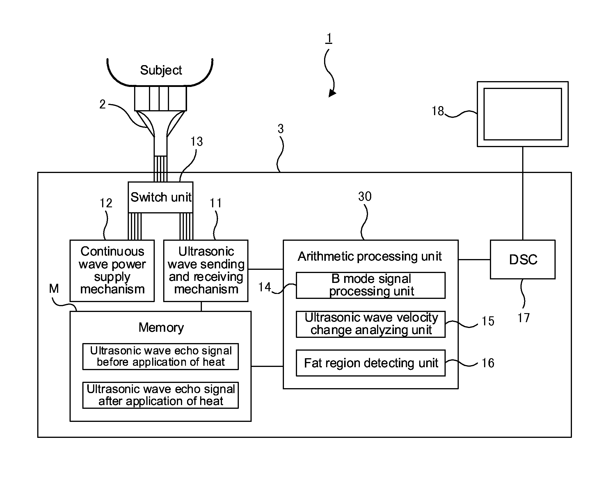
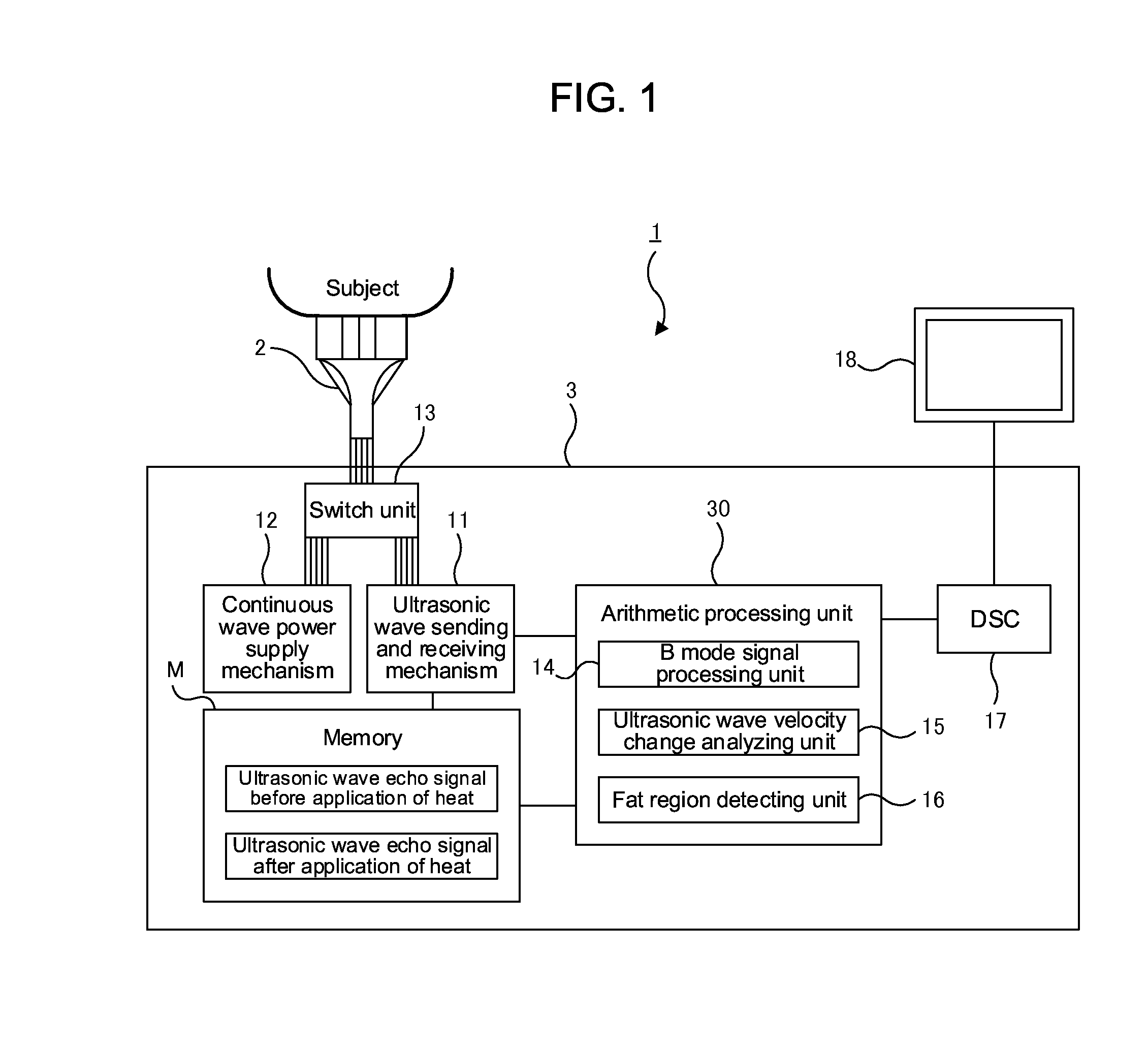
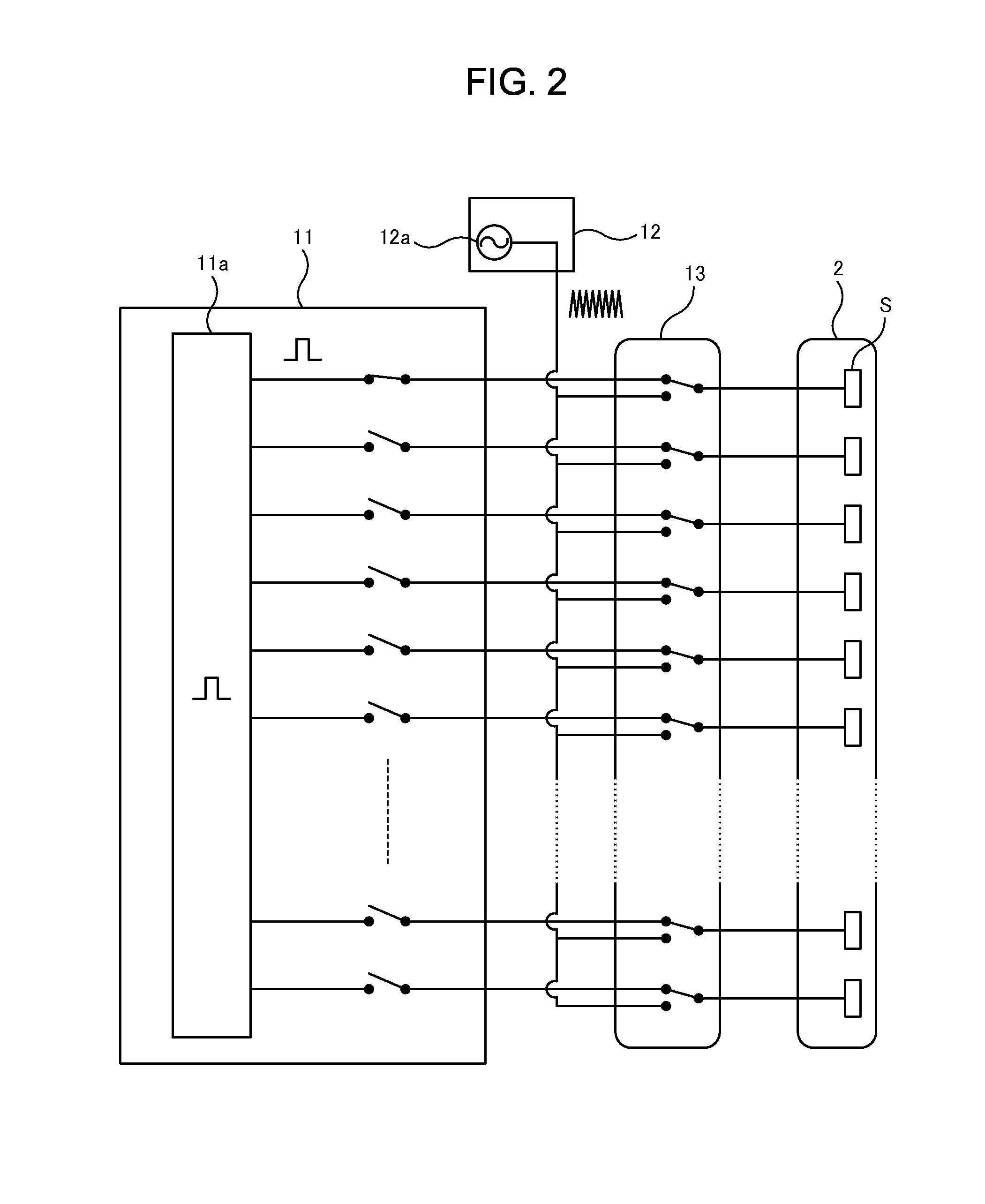
[0067]FIG. 1 is a block diagram showing the entire configuration of the body fat diagnostic apparatus according to one embodiment of the present invention, and FIG. 2 is a diagram showing a portion of the structure for sending and receiving ultrasonic waves for diagnosis and for sending continuous ultrasonic waves for applying heat using a probe in FIG. 1.

[0068]A body fat diagnostic apparatus 1 is made of a probe 2 and a control unit 3 for controlling the system in order to conduct an ultrasonic wave diagnosis, to apply heat and to conduct a fat diagnosis from the measurement of the change in the velocity of ultrasonic waves, using the probe 2.

[0069]The probe 2 is an array type probe (also referred to as an array transducer) where a number of (for example 128) piezoelectric elements that function as oscillators for sending and receiving waves to and from a subject are aligned i...

second embodiment

[0095]Though the ultrasonic wave source for applying heat and the ultrasonic wave source for diagnosis are switched by means of the switch unit 13 in all of the above described embodiments, alternatively, the same ultrasonic wave source may be used for applying heat and for diagnosis.

[0096]FIG. 5 is block diagram showing the entire configuration of a body fat diagnostic apparatus 1a according to another embodiment of the present invention, and FIG. 6 is a diagram showing a portion of the structure for sending and receiving ultrasonic waves for diagnosis and for sending ultrasonic waves for applying heat using a probe in FIG. 5.

[0097]In the control unit 3a in this embodiment, an ultrasonic wave sending and receiving mechanism 40 both for diagnosis and for power supply to apply heat having an improved ultrasonic wave drive circuit (driver) where the output voltage (amplitude of a signal), the waveform (duty cycle ratio of a pulse) and the phase can be greatly changed is used in place ...


PUM


Abstract

A body fat diagnostic apparatus with which fat can be diagnosed safely is provided even in the case where a deep portion of the living body is diagnosed or there are bone tissues outside the measurement region. The body fat diagnostic apparatus is formed of: a probe 2 for emitting ultrasonic waves both for applying heat and for diagnosis; and an ultrasonic wave velocity change analyzing unit 15 for calculating the change in the velocity of ultrasonic waves in the measurement region on the basis of the ultrasonic wave echo signals acquired from the region before and after the application of heat using the probe 2, so that fat is diagnosed on the basis of the calculated change in the velocity of ultrasonic waves.

Description

CROSS-REFERENCE TO RELATED APPLICATIONS[0001]This application claims priority to Japanese Patent Application No. 2014-052595 filed Mar. 14, 2014, the subject matter of which is incorporated herein by reference in entirety.BACKGROUND OF THE INVENTION[0002]1. Field of the Invention[0003]The present invention relates to a body fat diagnostic apparatus for applying heat to a measurement region such as a region of interest (ROI) of a subject so as to detect a change in the velocity of ultrasonic waves before and after the application of heat to the region, and thus, for diagnosing fat tissues. In particular, the present invention relates to a body fat diagnostic apparatus that is appropriate for fat diagnosis in a deep portion of the body, more specifically, for diagnosing fat inside the ribcage such as in the liver.[0004]2. Description of Related Art[0005]As a diagnostic technology for diagnosing the state within the body, a sound wave measuring apparatus for applying heat to a subject ...

Claims


Application Information

Patent Timeline
Patent Type & Authority Applications(United States)
IPC IPC(8): A61B8/08A61B8/00A61B8/14A61B5/00
CPCA61B8/5223A61B5/4872A61B8/14A61B8/5207A61B8/4483A61B8/08A61B8/48B06B1/0207G01S15/899G01S7/52036B06B2201/76G16H50/30Y02A90/10
Inventor HORINAKA, HIROMICHIMORIKAWA, HIROYASUIDA, TAIICHIRO
Owner PUBLIC UNIVERSITY CORPORATION OSAKA CITY UNIVERSITY
Why Eureka
Try Eureka