Ultrasound diagnostic apparatus and shear-elasticity measurement method therefor

Inactive Publication Date: 2014-05-29
HITACHI LTD
View PDF2 Cites 9 Cited by
  • Summary
  • Abstract
  • Description
  • Claims
  • Application Information

AI Technical Summary

Benefits of technology

[0009]In this arrangement, the apparatus can invite attention of the examiner by displaying such temperature information, so that the rise in temperature of a physiological object can be suppressed within a predetermined range for a safe measurement of the shear elasticity of the biological tissue under ultrasound irradiation.
[0010

Problems solved by technology

However, the biological tissue will be then overheated and necrotized if the ultrasound energy deposite

Method used


Image

  • Ultrasound diagnostic apparatus and shear-elasticity measurement method therefor
  • Ultrasound diagnostic apparatus and shear-elasticity measurement method therefor
  • Ultrasound diagnostic apparatus and shear-elasticity measurement method therefor

Examples


first embodiment

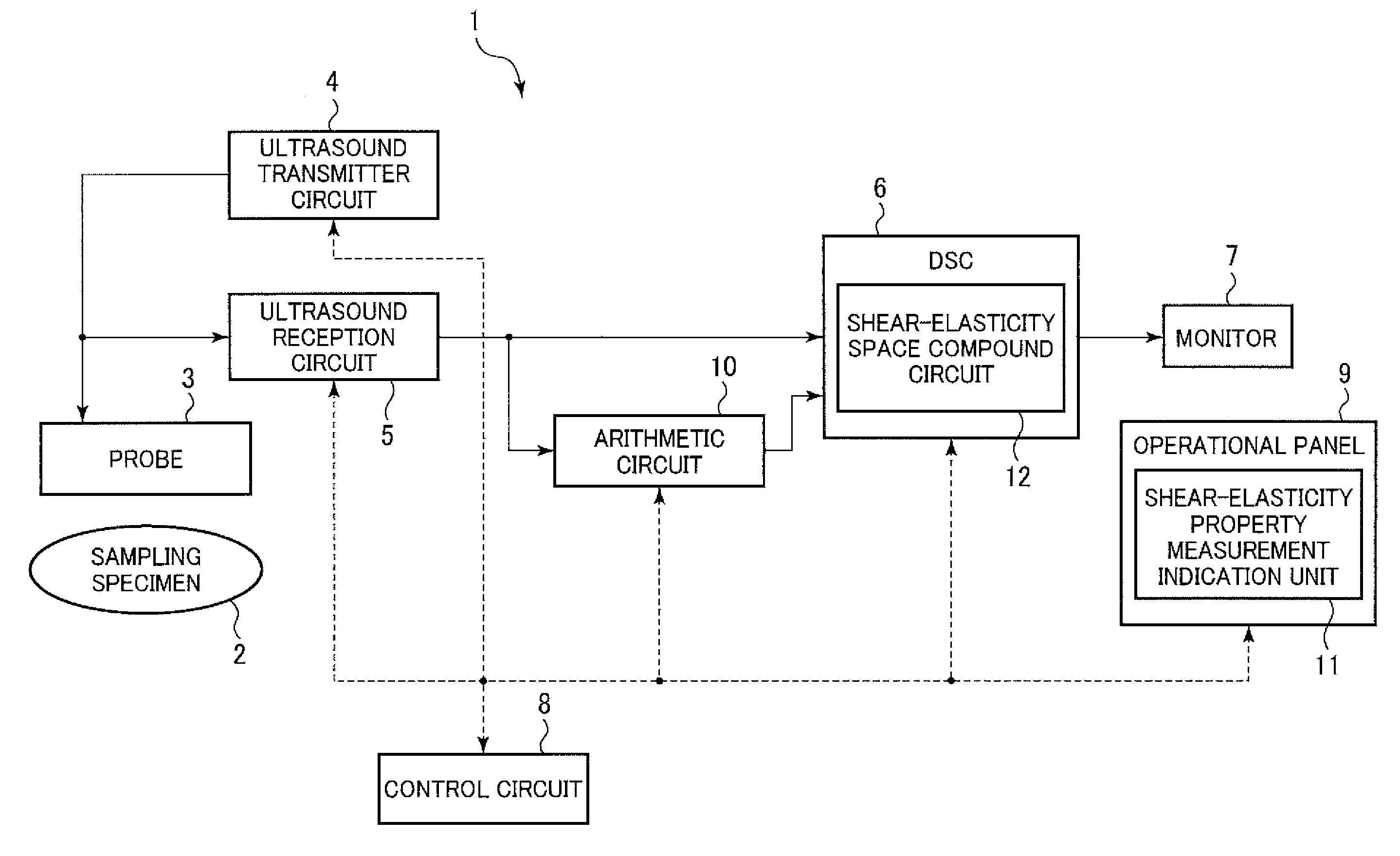
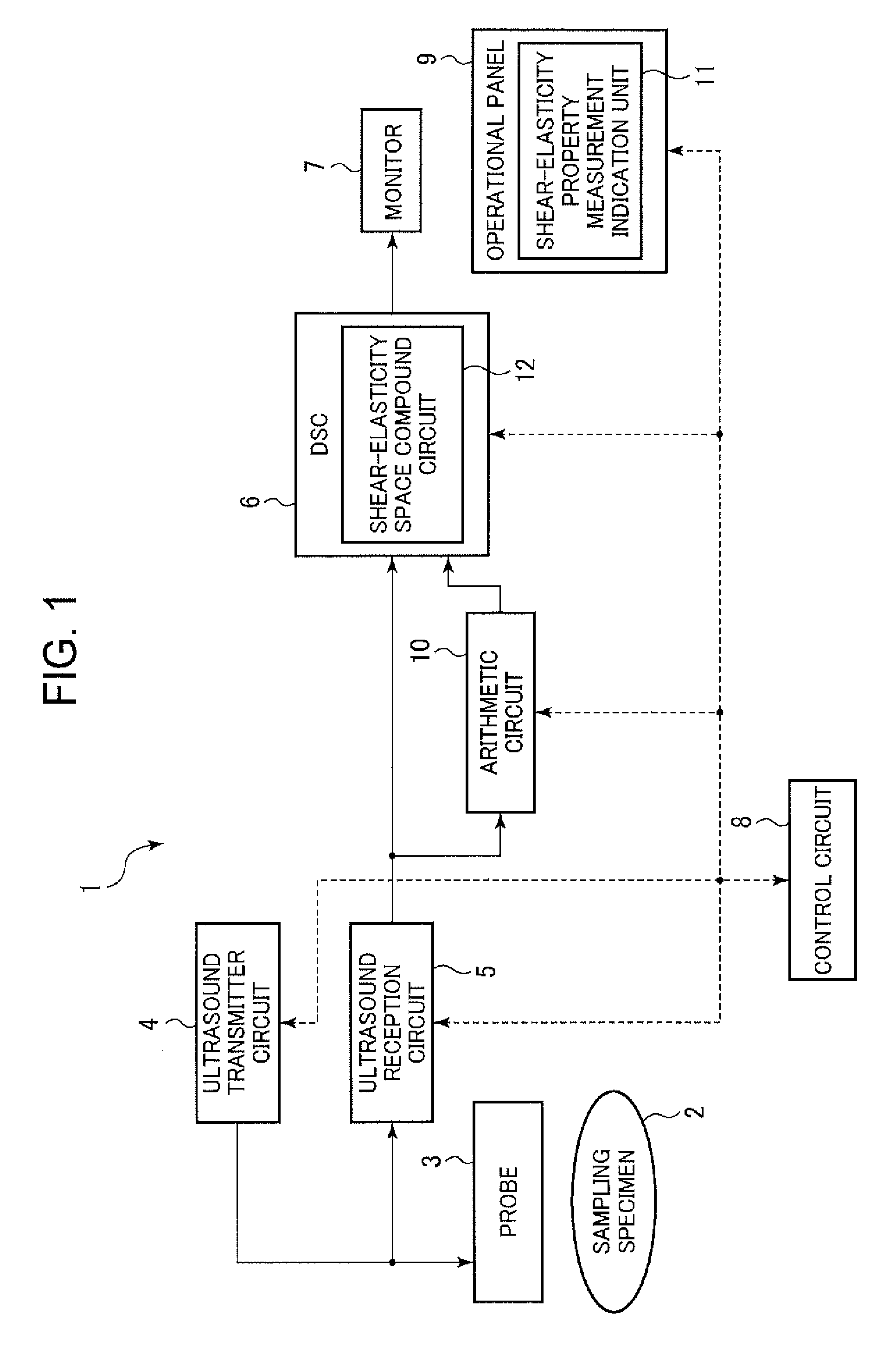
[0020]The ultrasound diagnostic device in accordance with a first embodiment of the invention will now be described in detail with reference to the accompanying drawings. FIG. 1 briefly shows a first mode of the inventive ultrasound diagnostic device.

[0021]This ultrasound diagnostic device 1 has a probe 3, an ultrasound transmitter circuit 4, an ultrasound receiving circuit 5, a digital scanning converter (DSC) 6, a monitor (display unit) 7, a control circuit (control unit) 8, an operation panel 9, and a calculation circuit (calculation unit) 10. The DSC 6 has a shear-elasticity space compound circuit 12. The operation panel 9 has a shear-elasticity property measurement-indication unit 11.

[0022]The probe 3 has an ultrasound oscillator unit which comprises a plurality of oscillators configured to emit ultrasound waves to an object (a sampling specimen) 2. The probe 3 can be a linear array of probes each equipped with a reed shape oscillator, or a 2-dimensional array of probes. The ul...

second embodiment

[0049]An ultrasound diagnostic device in accordance with a second embodiment of the invention will now be described in detail with reference to the accompanying drawings. Other structural features of the second embodiment are similar to those of the first embodiment unless otherwise stated. FIG. 3 briefly illustrates how ultrasound wave is irradiated by the ultrasound diagnostic device in accordance with this embodiment.

[0050]FIG. 3(a) shows a single beam B1 of ultrasound wave irradiating the object 2 in one direction to cause a biological shear stress therein. In order to generate transverse waves at different depths in a biological region for the purpose of causing a shear stress in that region, such US beam B1 is focused onto multiple focusing points f at different depths in sequence. A depth-wise region that includes those multiple focusing points f is referred to as focusing region F. When an ultrasound wave beam B1 is irradiated to a biological tissue in one direction as shown...

third embodiment

[0065]Referring to FIG. 6, there is shown an ultrasound diagnostic device in accordance with a third embodiment of the invention. Features of the third embodiment are the same as those of the first and second embodiments unless otherwise stated. FIG. 6 is an overview of shear elasticity images obtained by the ultrasound diagnostic device in accordance with the third embodiment. The control circuit 8 determines whether or not the shear elasticity calculation is needed for the focusing regions F6-F8 based on at least one of the biological displacements caused by longitudinal ultrasound wave and transverse ultrasound wave in the focusing regions F6-F8. If the control circuit 8 determines that the shear elasticity need not be calculated for the focusing regions F6-F8, the calculation circuit 10 calculates shear elasticity in the measurement domain E other than the focusing regions F6-F8, excluding those measurement domains E1-E3 that belong to the focusing regions F6-F8.

[0066]As describ...


PUM


Abstract

An inventive ultrasound diagnostic device is provided, which can display information on the temperature rise in a biological object under ultrasound radiation for measurement of a shear elasticity of a biological tissue of interest, thereby drawing attention of an examiner of the device and enabling him to retain the temperature rise within a predetermined safe range while performing the shear elasticity measurement. The device is adapted to measure the shear elasticity of a tissue by ultrasonic waves emitted from a probe. The device has a calculation unit configured to calculate a rise in temperature of the biological tissue irradiated with a focused ultrasonic (US) beam, and a display unit configured to display the temperature information obtained.

Description

TECHNICAL FIELD[0001]This invention relates to an ultrasound diagnostic device and a method for measuring the shear-elasticity of a biological tissue, particularly capable of reducing temperature rise in the biological domain irradiated with ultrasound wave while safely measuring such shear-elasticity.BACKGROUND ART[0002]It has been well known in the art that a biological tissue afflicted by a tumor (for example, breast cancer and prostatic cancer) significantly hardens as the tumor grows as compared with healthy tissues. It is also known that in a region afflicted by such tumor a transverse ultrasound has an increased speed. Thus, there has been proposed a method of discerning a tumor-afflicted biological region by transmitting an ultrasound wave through the region and measuring the ultrasound shear rate of the domain. (See for example, Patent Document 1 listed below.)PRIOR ART DOCUMENTSPatent Document[0003]Patent Document 1: U.S. Pat. No. 6,951,544SUMMARY OF INVENTIONObjects to be...

Claims


Application Information

Patent Timeline
IPC IPC(8): A61B8/00A61B5/01A61B8/08
CPCA61B8/485G01S7/52042G01S7/52036G01S7/52074A61B5/01A61B8/461A61B8/085A61B8/5223A61B8/546
Inventor TAMANO, SATOSHI
Owner HITACHI LTD
Why Eureka
Try Eureka