Tank container

a technology for tank containers and liners, applied in the field of tank containers, can solve the problems of destroying the protective effect of tank linings, not being suitable for some cargoes,

Inactive Publication Date: 2015-09-17
WEW WESTERWAELDER EISENWERK
View PDF2 Cites 3 Cited by
  • Summary
  • Abstract
  • Description
  • Claims
  • Application Information

AI Technical Summary

Problems solved by technology

The tank construction materials, such as fine-grained structural steels or chromium nickel steels normally used for tank containers, are not suitable for some cargoes, because they are too badly attacked by such content materials.
However, as a rule, they are not suitable to absorb the loads to be transferred between the frame and the tank.
However, there also known such coatings and linings which are very brittle, such that even the slightest deformations give rise to cracks (e.g. vitreous enamel) or crystalline dislocations, which destroy the protective effect of such linings, because the content material then passes through the damaged inner coating to the container construction material, causing its decomposition.
However, its passive layer forming the corrosion barrier is very brittle, and its structure is damaged even if minor deformations take place, and then no longer serves as a tight barrier.
These known support means are however heavy and their manufacture is expensive.
Moreover, the weight of the container which, as a result of the leading lining is already greatly increased, is further increased by the required heavy support and frame construction, and the already limited transport volume is further diminished.
The known end frame constructions are only suited to a limited extent to their employment with lead-lined vessels, because there is a risk that, due to the comparatively small contact area between the annular support structure and the bottom, high stresses arise due to load effects.
As a result thereof, the bottom is deformed to such an extent that the internal lead lining is damaged and can no longer be effective as a protective barrier between the content material (bromine) and the vessel.
A conceivable partial solution would be to increase the wall thickness of the domed end bottoms to such an extent that the arising loads can no longer result in effective deformation.
However, this would result likewise in a considerable weight increase, which is undesirable.

Method used


Image

  • Tank container
  • Tank container

Examples


Embodiment Construction

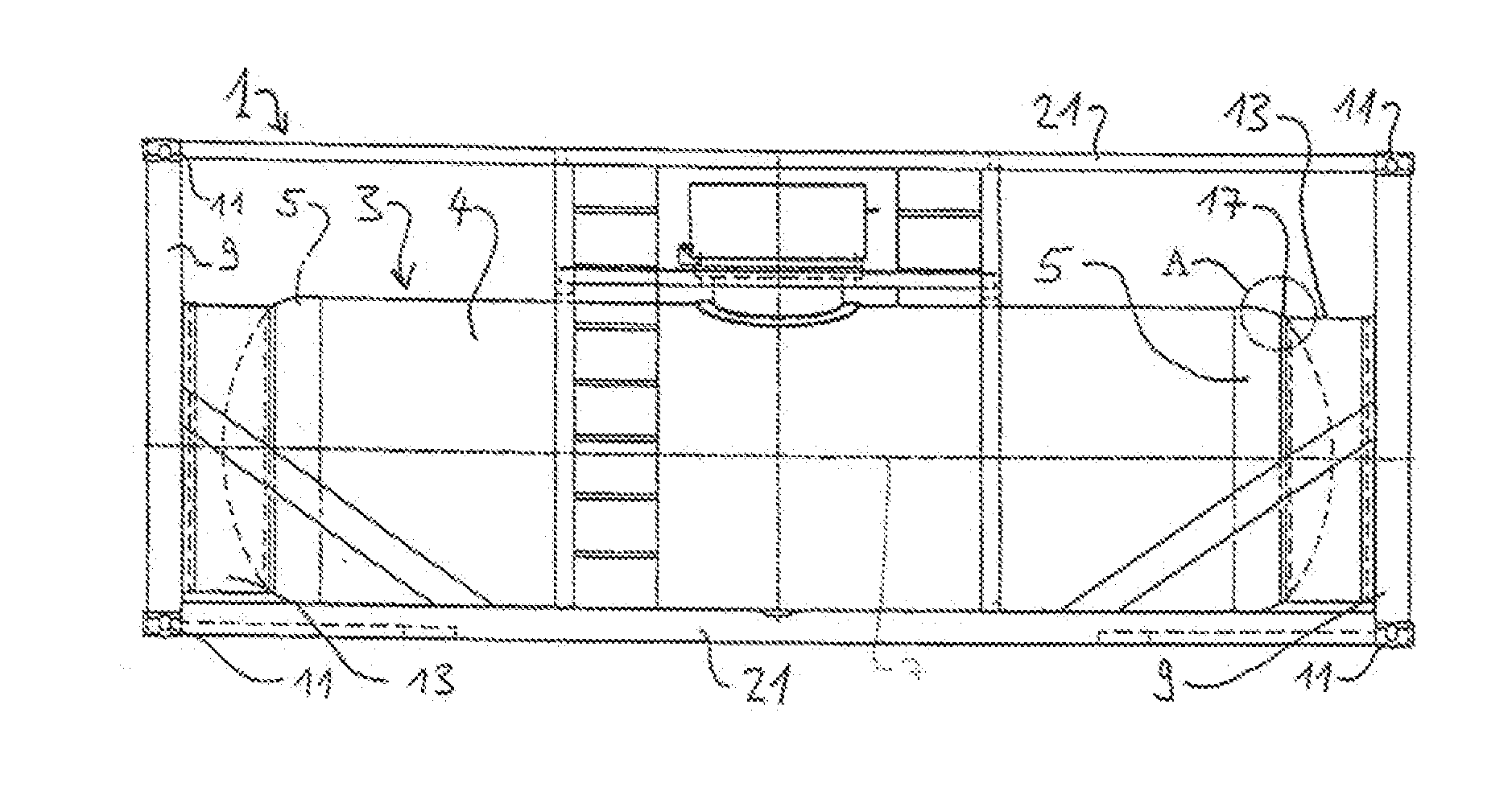
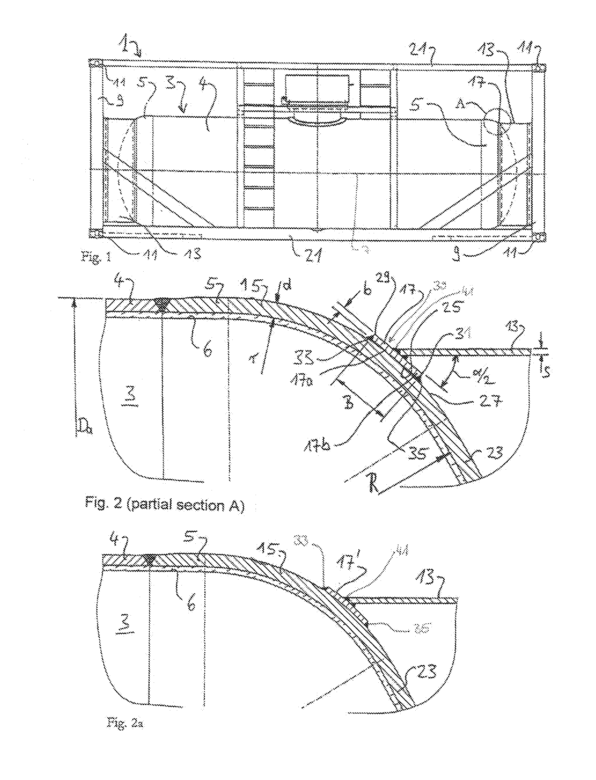
[0018]FIGS. 1 and 2 show an embodiment according to the invention. Prior to their detailed description, some general elucidations of further embodiments are provided in what follows.

[0019]In an embodiment of the tank container, the angle of conicity a of the annular support is between 60° and 100° and preferably between 70° and 90°. In that manner, the load application, in particular of loads acting in the longitudinal direction, is improved. This is so because in that manner the load component acting longitudinally is applied further outwardly and in longitudinal direction into the cylindrical jacket. The deformation effect of such loads onto the bottom is minimized.

[0020]In an embodiment, in which a width B of the annular support is so provided that it covers between 20% and 30% of the exterior area of the rim region, the load transfer surface (the broad surface of the annular support, i.e. the inner side of the cone) is so large that a very effective load distribution over the bo...


PUM


Abstract

The invention relates to a tank container (1) including a cylindrical vessel (3), the ends of which are closed by domed bottoms (5), and provided with an inner lining (6), in particular lead lining, and being connected at the bottoms (5) in each case by way of an annular device (13) to an end frame device (9). The annular device (13) is provided in a rim region (15) of the bottom (5). Between the annular device (13) and the bottom, in the rim region (15), a frustoconical annular support element (17, 17′) extends concentrically to the annular device (13). It engages flush by way of a broad side (25) with the outside (27) of the rim region (15) and is fixed on its inner and outer edge (29, 31) by way of welding seams (33, 35) to the rim region (15), such that loads acting between the vessel (3) and the annular device (13) are transmitted by way of the broad side (25) between the vessel (3) and the annular support element (17, 17′).

Description

FIELD OF THE INVENTION[0001]The present invention relates to a tank container including a cylindrical vessel, the ends of which are closed by domed bottoms and which includes an inner lining, in particular, a lead coating.BACKGROUND OF THE INVENTION[0002]Tank containers are employed for the transportation of a variety of chemical products. In this context, in known tank container constructions a horizontally-disposed, cylindrical vessel is connected at its ends by way of a support structure to end frames. Such a support structure is, for example, known from DE 78 06 797 U1. The end frames by way of their corner castings provide the interface for transportation and transloading of the tank container. Usually, the support structure takes the form of an annular device, which is welded to the portion of the tank bottom surrounded by the rim region and which is connected at its opposite end to the end frame. The tank bottoms usually take the form of torispherically-curved bottoms (e.g. d...

Claims


Application Information

Patent Timeline
Patent Type & Authority Applications(United States)
IPC IPC(8): F17C3/12
CPCF17C3/12F17C2201/0104F17C2203/0653F17C2203/0604F17C2203/012B65D88/12B65D88/128
Inventor PFAU, DIETERTANNENBERGER, KEVIN
Owner WEW WESTERWAELDER EISENWERK
Why Eureka
Try Eureka