

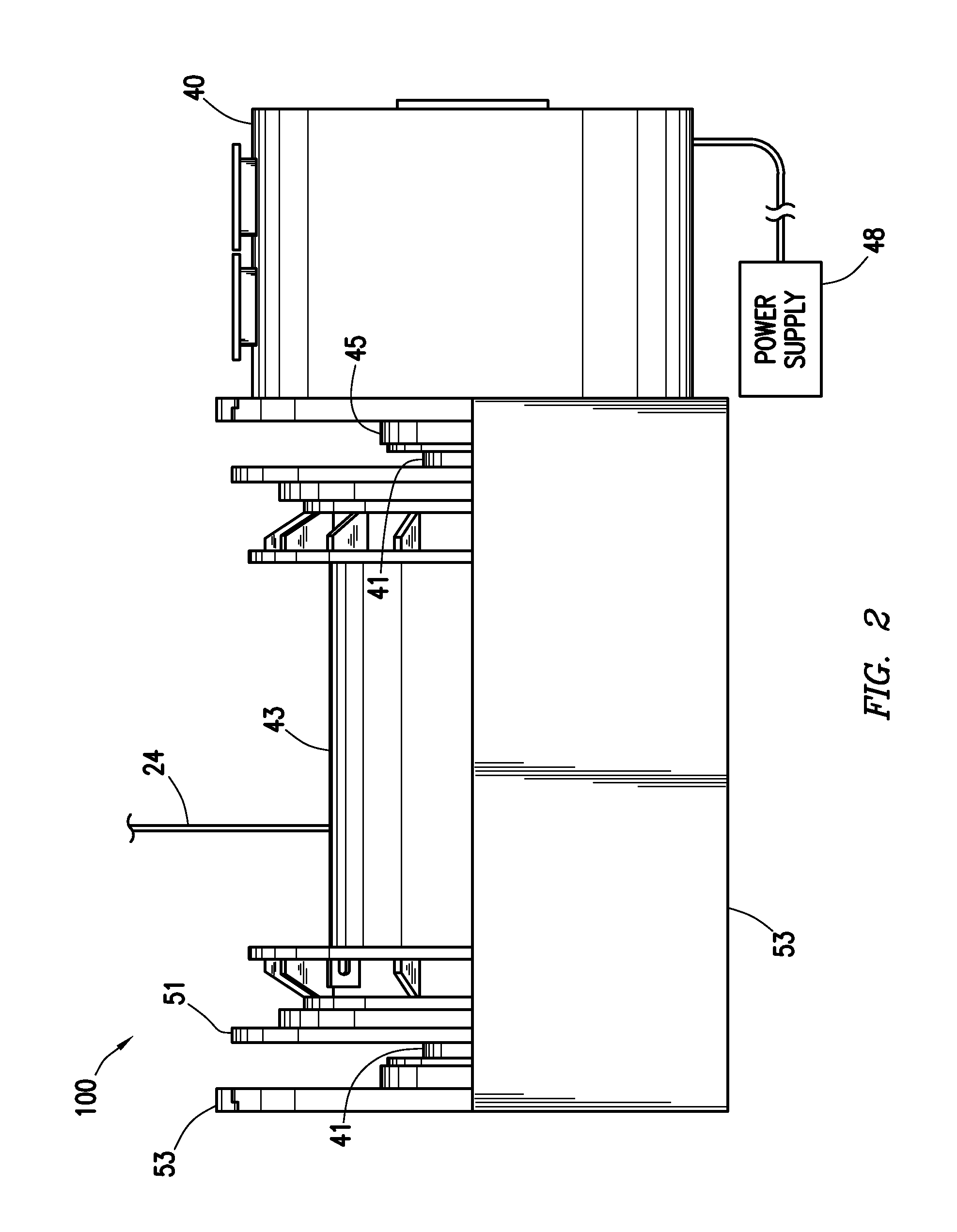
Low Inertia Direct Drive Drawworks
a direct drive, low inertia technology, applied in the direction of hoisting equipment, magnetic circuit shape/form/construction, hoisting equipment, etc., can solve the problem of large amount of energy wasted, and achieve the effect of low inertia
- Summary
- Abstract
- Description
- Claims
- Application Information
AI Technical Summary
Benefits of technology
Problems solved by technology
Method used
Image

Examples
Embodiment Construction
[0016]It is to be understood that the following disclosure provides many different embodiments, or examples, for implementing different features of various embodiments. Specific examples of components and arrangements are described below to simplify the present disclosure. These are, of course, merely examples and are not intended to be limiting. In addition, the present disclosure may repeat reference numerals and / or letters in the various examples. This repetition is for the purpose of simplicity and clarity and does not in itself dictate a relationship between the various embodiments and / or configurations discussed.
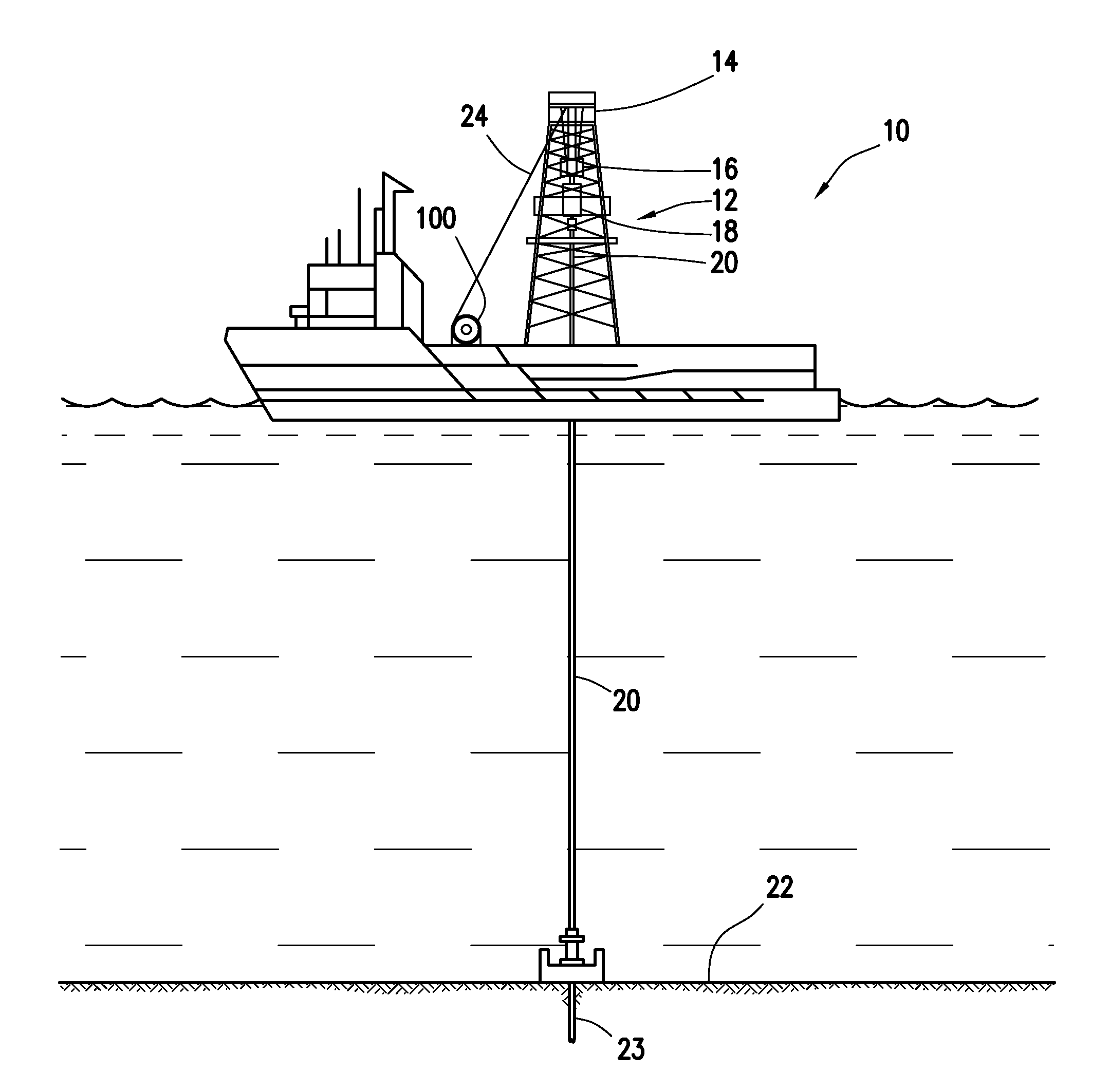
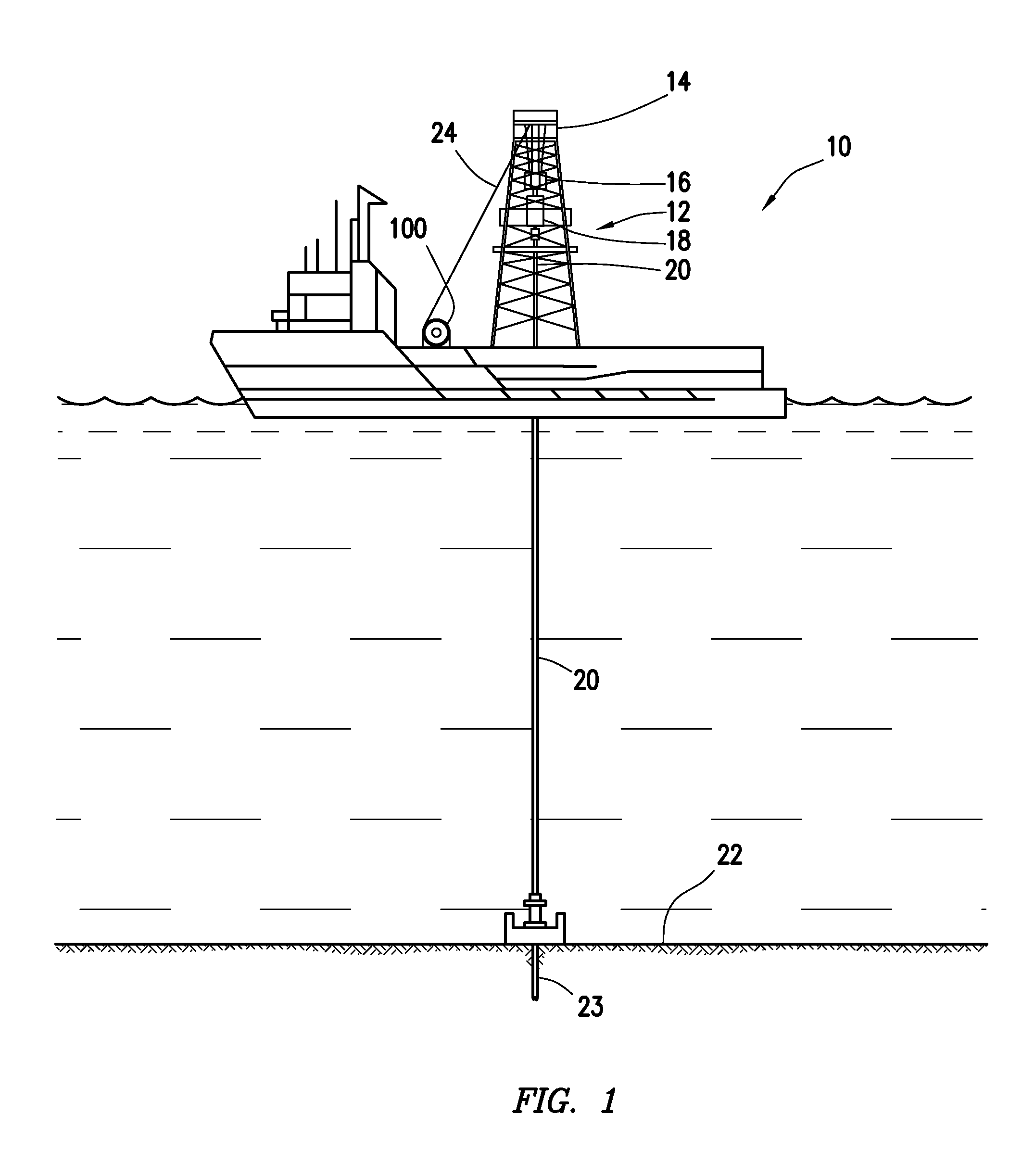
[0017]FIG. 1 depicts floating drilling platform 10. In this figure, floating drilling platform 10 is a drill ship. One having ordinary skill in the art with the benefit of this disclosure will understand that any floating drilling platform may be substituted for the drill ship depicted. Floating drilling platform 10 may include derrick 12. Derrick 12 may be positioned ...
PUM
 Abstract
Description
Claims
Application Information