Adjustable sensor support structure for optimizing skin contact

a sensor and support structure technology, applied in the field of skin contact optimization, can solve problems such as creating the potential for misinterpretation of ecg readings, and achieve the effect of improving contact quality

Inactive Publication Date: 2015-09-24
SAMSUNG ELECTRONICS CO LTD
View PDF7 Cites 41 Cited by
  • Summary
  • Abstract
  • Description
  • Claims
  • Application Information

AI Technical Summary

Benefits of technology

[0007]Exemplary embodiments provide an adjustable sensor support structure for optimal skin contact. Aspects of the exemplary embodiments include a sensor array comprising a plurality of sensor units arranged on a band such that the sensor array straddles or otherwise addresses a blood vessel when worn on a measurement site of a user; and a pressure exertion apparatus attached between the sensor units and the band that exerts outward pressure on the sensor units towards the measurement site causing the sensor units to maintain contact with skin of the user independent of motion activity of the band, thereby improving contact quality, wherein the pressure exertion apparatus comprises at least one of: a flexible bridge structure, a flexible foam structure, and a sensor trampoline structure.

Problems solved by technology

A motion artifact is noise that results from motion of the electrode in relation to the user's skin (i.e. electrode movement causes deformations of the skin around the electrode site in turn causing a change in the electrical characteristics of the skin about the electrode) and may make a contribution to the ECG reading that is not related to cardiac activity, thus creating the potential for misinterpretation of the ECG reading.
Motion artifacts are an especially major technical challenge faced when making ECG measurements in a mobile or portable application, as well as with heart rate detection, as dealing with a high level of noise introduced by motion artifacts becomes an increased component of the overall measured signal.

Method used


Image

  • Adjustable sensor support structure for optimizing skin contact
  • Adjustable sensor support structure for optimizing skin contact
  • Adjustable sensor support structure for optimizing skin contact

Examples


Embodiment Construction

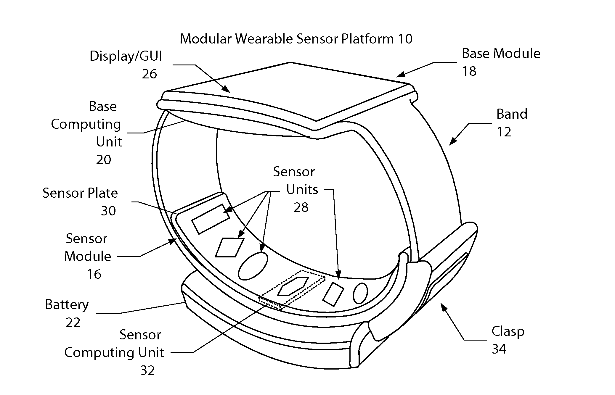
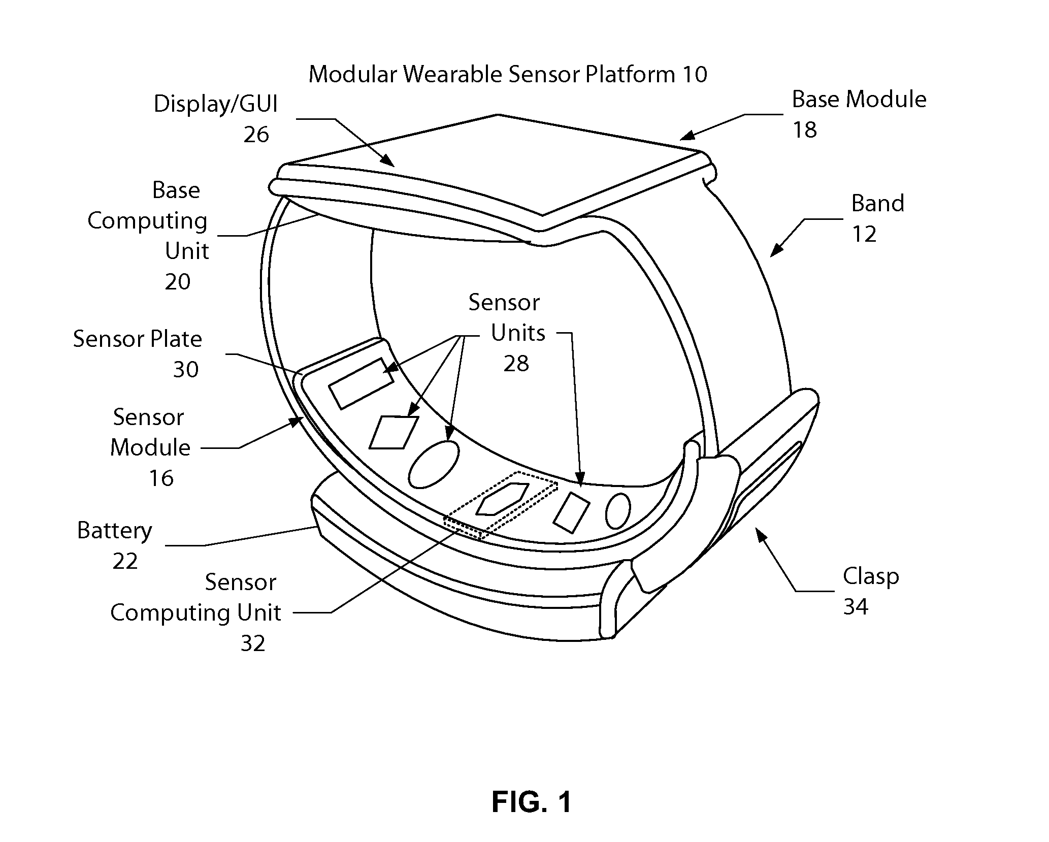
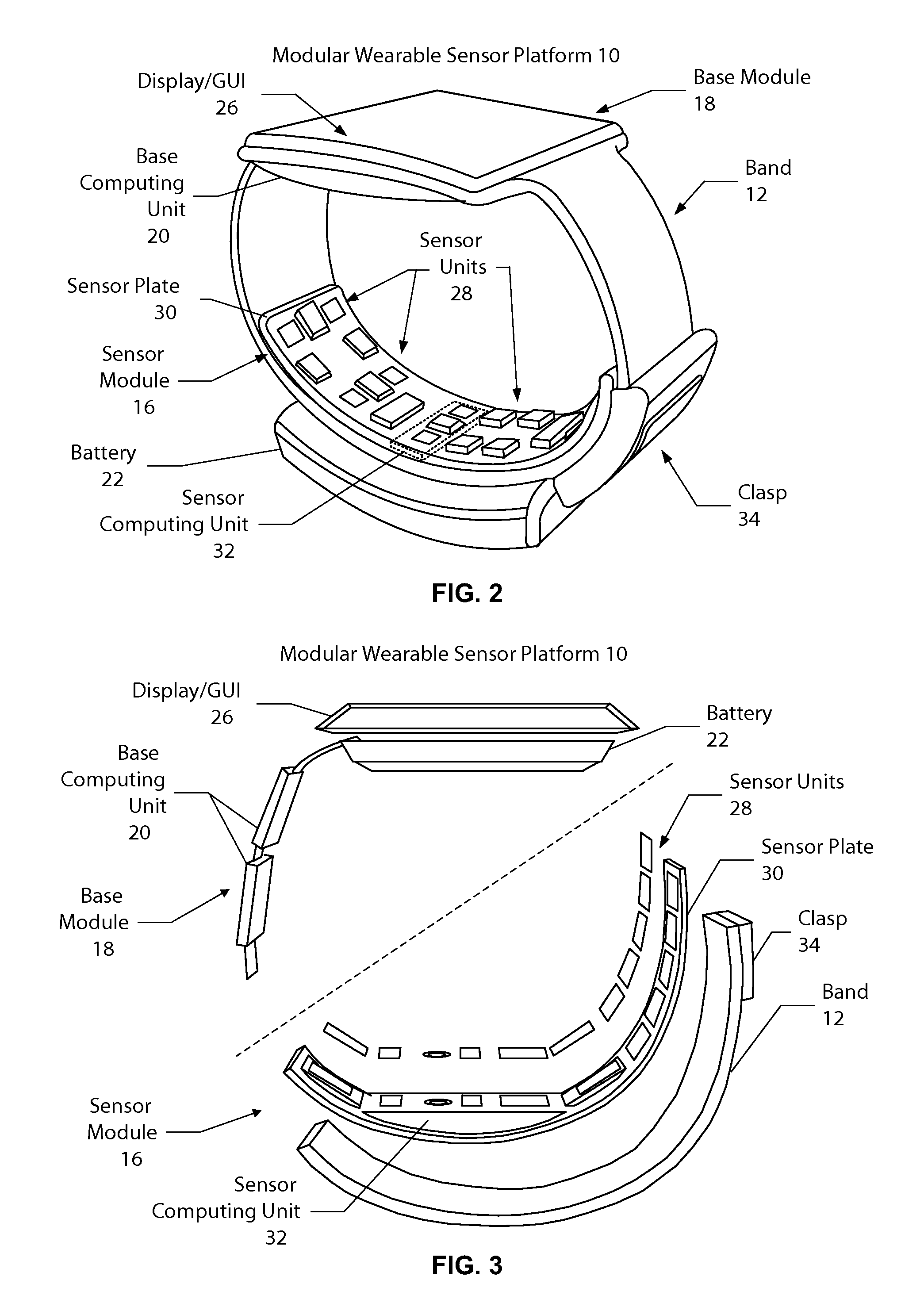
[0024]Reference will now be made in detail to the embodiments of the present general inventive concept, examples of which are illustrated in the accompanying drawings, wherein like reference numerals refer to the like elements throughout. The embodiments are described below in order to explain the present general inventive concept while referring to the figures.

[0025]Advantages and features of the present invention and methods of accomplishing the same may be understood more readily by reference to the following detailed description of embodiments and the accompanying drawings. The present general inventive concept may, however, be embodied in many different forms and should not be construed as being limited to the embodiments set forth herein. Rather, these embodiments are provided so that this disclosure will be thorough and complete and will fully convey the concept of the general inventive concept to those skilled in the art, and the present general inventive concept will only b...


PUM

PropertyMeasurementUnit
distanceaaaaaaaaaa
flexibleaaaaaaaaaa
shapeaaaaaaaaaa

Abstract

Exemplary embodiments provide an adjustable sensor support structure for optimal skin contact. Aspects of the exemplary embodiments include a sensor array comprising a plurality of sensor units arranged on a band such that the sensor array straddles or otherwise addresses a blood vessel when worn on a measurement site of a user; and a pressure exertion apparatus attached between the sensor units and the band that exerts outward pressure on the sensor units towards the measurement site causing the sensor units to maintain contact with skin of the user independent of motion activity of the band, thereby improving contact quality, wherein the pressure exertion apparatus comprises at least one of: a flexible bridge structure, a flexible foam structure, and a sensor trampoline structure.

Description

CROSS-REFERENCE TO RELATED APPLICATIONS[0001]The present application claims the benefit of U.S. Provisional Application No. 61 / 969,766, filed on Mar. 24, 2014, which is incorporated herein by reference in its entirety.BACKGROUND[0002]Physiological data may be obtained through various measurements such as photoplethysmograph (PPG), electrocardiogram (ECG), bioimpedance, and others which may be implemented in a portable device.[0003]For example, heart rate may be measured by detecting the impedance changes caused by a pulse in blood flow within a local area of the body. Heart rate detection through measurement of the electrical properties of flowing blood may be achieved by measuring the potential created by current passed through the blood, artery, and surrounding tissue. Conventional wearable heart rate detectors utilizing an impedance sensing scheme are often worn at or near the chest using a chest band. In another conventional implementation, the heart rate detector may instead be...

Claims


Application Information

Patent Timeline
Patent Type & Authority Applications(United States)
IPC IPC(8): A61B5/00H05K3/10A61B5/1455A61B5/0205A61B5/0408
CPCA61B5/6843A61B5/02055A61B5/0408H05K3/10A61B5/7475A61B5/0015A61B5/14552A61B5/742A61B5/0205A61B5/681A61B5/25H05K1/189H05K3/103H05K2201/10151Y10T29/49155Y10T29/49826
Inventor DE KOK, MARGREETBROWN, LINDSAYVAN HECK, GERTPHILLIPS, SHELDON GEORGEKOPP, JR., JOSEPH J.
Owner SAMSUNG ELECTRONICS CO LTD
Why Eureka
Try Eureka