
Partial-load de-rating for wind turbine control

a wind turbine and partial load technology, applied in the direction of wind turbines, engine control, motors, etc., can solve the problems of limited aerodynamic power, upper limit of how much power the turbine can generate at that wind speed, and limited power b>12/b> in the low wind region,

Inactive Publication Date: 2015-09-24
VESTAS WIND SYST AS
View PDF9 Cites 31 Cited by
  • Summary
  • Abstract
  • Description
  • Claims
  • Application Information

AI Technical Summary

Benefits of technology

This patent describes a method for controlling a wind turbine to capture as much wind power as possible while still producing a steady power output. This is accomplished by adjusting the blade pitch of the rotor based on a power reference signal, which directs the rotor to capture wind power that is about equal to the requested power output level. The method also includes adjusting the load torque provided to the rotor by the generator to control the output power level of the wind turbine. Additionally, the patent also describes a de-rated power output level that can be achieved by adjusting the pitch of the turbine to reduce the power coefficient of the rotor below an optimal level. This allows the wind turbine to operate more efficiently at varying wind speeds.

Problems solved by technology

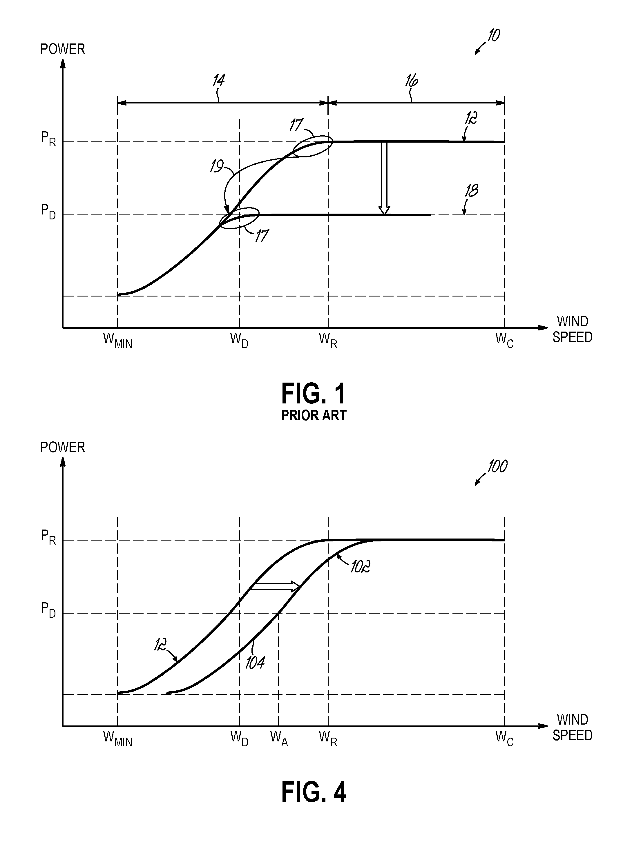
This optimal power coefficient thus sets an upper limit on how much power the turbine can generate at that wind speed.
However, as the wind speed increases above WR, aerodynamic power is limited by adjusting the blade pitch to reduce Cp.
Thus, the available power 12 in the low wind region 14 is limited by the wind power that the rotor can capture while operating at optimal blade pitch and rotational speed.
Conventionally controlled wind turbine systems may therefore experience greater pitch system wear under de-rated operation than during full power operation.

Method used


Image

  • Partial-load de-rating for wind turbine control
  • Partial-load de-rating for wind turbine control
  • Partial-load de-rating for wind turbine control

Examples


Embodiment Construction

[0025]Generally, the embodiments of the invention are directed to control methods and systems for wind energy applications that reduce the amount of pitching required to maintain desired power output levels.

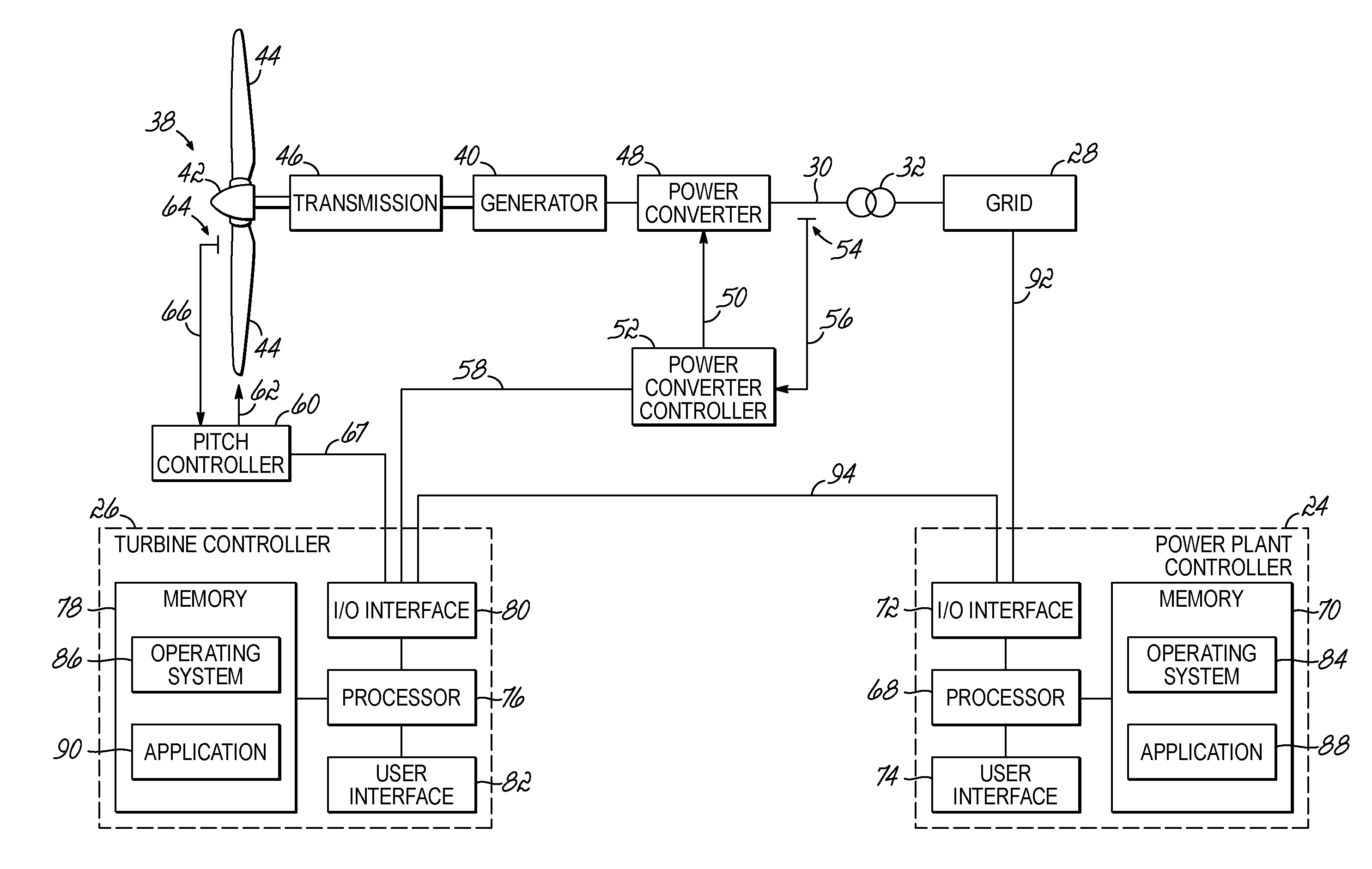
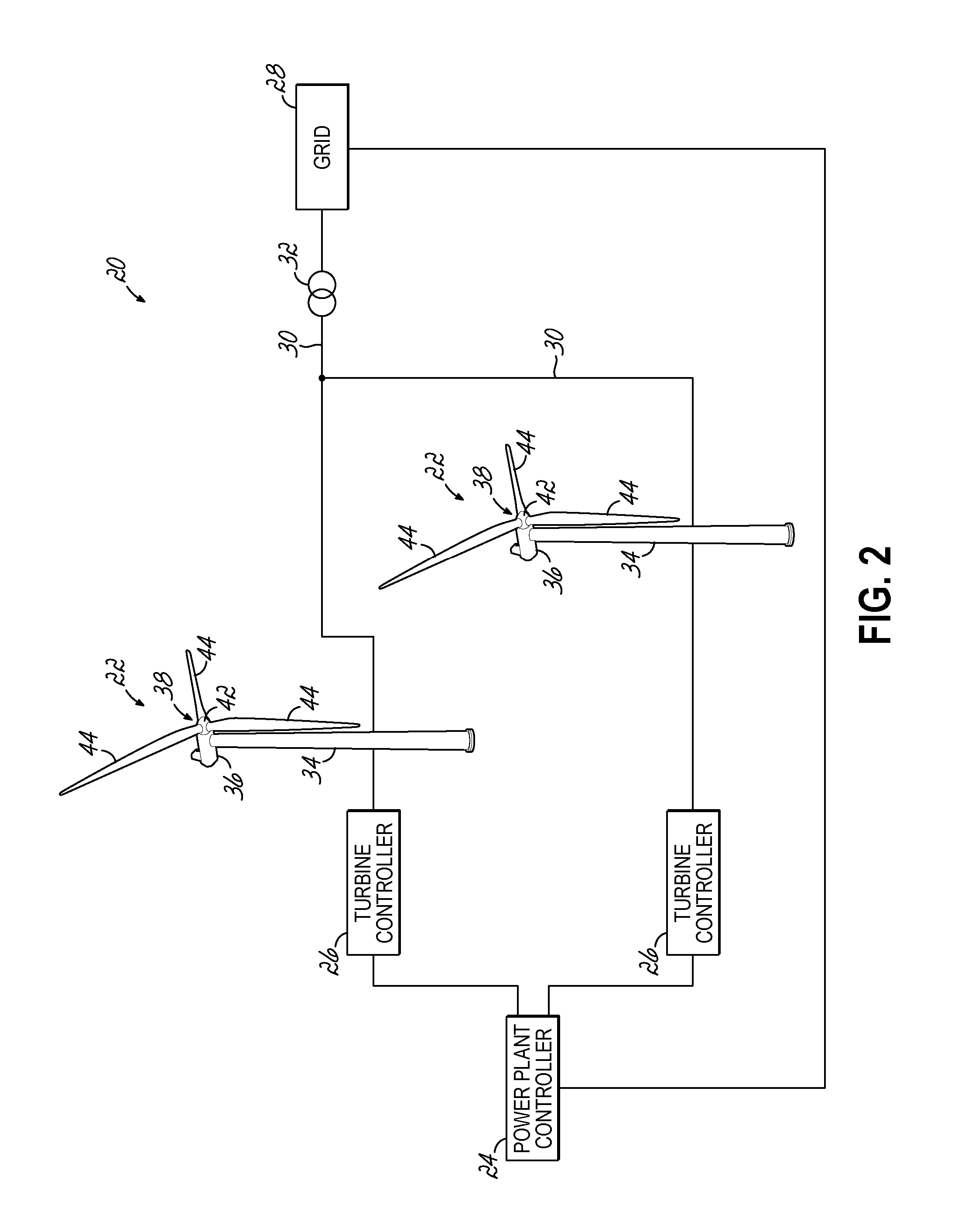
[0026]Referring now to FIG. 2, an exemplary wind farm 20 includes a plurality of wind turbines 22 and a power plant controller 24 in communication with a plurality of wind turbine controllers 26. The wind turbines 22 may be electrically coupled to the electrical grid 28 via an internal wind farm grid 30 that is electrically coupled to the electrical grid 28 at a common point of connection 32. Each wind turbine 22 may include a tower 34, a nacelle 36 disposed at the apex of the tower 34, and a rotor 38 operatively coupled to a generator 40 (FIG. 3) housed inside the nacelle 36. In addition to the generator 40, the nacelle 36 may house various components needed to convert wind energy into electrical energy and also various components needed to operate and optimize the performance o...


PUM


Abstract

Methods, controllers and computer program products for controlling a wind turbine. Under de-rated operating conditions in which the power requested from a wind turbine is less than the available power, a controller adjusts blade pitch of the wind turbine to reduce the rotor power coefficient. The captured wind power is thereby reduced to be approximately equal to the requested electrical power, which is less than either the available power or the rated power of the wind turbine generator. This reduction in captured power provides the controller with an additional degree of freedom that allows the controller to increase the electrical power output of the wind turbine in response to wind fluctuations without damaging the wind turbine. By allowing increases in power under de-rated conditions, the controller may reduce the amount of pitching necessary to prevent the turbine from exceeding its rated power output level.

Description

TECHNICAL FIELD[0001]This application relates generally to methods and systems for controlling wind turbines and, more specifically, to methods and systems for controlling the power output of wind turbine generators under de-rated operating conditions.BACKGROUND[0002]Generally, a wind turbine is a rotating machine that converts the kinetic energy of wind into mechanical energy and, when used for power generation, converts this mechanical energy into electrical energy. Due to their ability to generate electrical power without consuming fossil fuels, wind turbines are increasingly being used as an alternative energy source for providing power to the electrical grid. A wind turbine used for electrical power generation typically includes a rotor having a plurality of blades configured to capture wind power. The rotor is coupled to a generator that converts the rotational energy of the rotor into electrical energy. As the wind speed increases above the minimum or “cut-in” speed (WMIN) fo...

Claims


Application Information

Patent Timeline
IPC IPC(8): F03D7/02F03D9/00
CPCF03D7/0284F03D9/003F03D7/0224F03D9/255F03D7/0272F03D7/028F05B2270/1033F05B2270/337Y02E10/72F03D9/257
Inventor KJ.AE BUTTED.R, MARTIN ANSBJERGHERBSLEB, EIK
Owner VESTAS WIND SYST AS
Learn More