Aerosol mobility imaging for rapid size distribution measurements

a technology of airborne particles and mobility imaging, which is applied in the direction of gas analyser construction details, instruments, testing water, etc., can solve the problems of limited sizing resolution, limited detection of lower concentrations, and electrometer based instruments that have neither the sizing precision nor the sensitivity for atmospheric measurements

Active Publication Date: 2015-09-24
AEROSOL DYNAMICS INC +1
View PDF2 Cites 10 Cited by
  • Summary
  • Abstract
  • Description
  • Claims
  • Application Information

AI Technical Summary

Problems solved by technology

These instruments can measure complete size spectra at 1 Hz-10 Hz, but their size resolution is limited by the multiple charging associated with the use of a unipolar charger, and the lower concentration they can detect is limited by electrometer noise (Jeong and Evans, 2009).
While they offer high time resolution, these electrometer based instruments have neither the sizing precision nor the sensitivity for atmospheric measurements, where particle concentrations aloft are often of the order of a 103 cm−3.
The differential mobility methods are capable of measurements at low particle concentrations, but are slow, requiring several minutes to complete each size distribution measurement.
The electrometer-based methods are fast, but are unable to detect particles at low concentrations typical of the atmosphere, especially in background or remote locations.
None of these currently available technologies provide both the time resolution and the sensitivity needed for precise, rapid measurements at typical atmospheric concentrations.

Method used


Image

  • Aerosol mobility imaging for rapid size distribution measurements
  • Aerosol mobility imaging for rapid size distribution measurements
  • Aerosol mobility imaging for rapid size distribution measurements

Examples


first embodiment

[0047]In one embodiment, the AMI system growth cell 30 is a Water Condensation Growth Cell, generally 100. in a first embodiment, two parallel plates are lined with a porous ceramic wick, and are positioned such that the interior width of the gap between the plates was about 11 mm. The overall length was selected at about 130 mm. It will be appreciated that these measurements are merely exemplary and not limiting on the scope of the present disclosure. To reduce the possibility of condensation on the optical components, we introduce a new “conditioner-initiator-equilibrator” architecture, for example as described in U.S. patent application Ser. No. 13 / 218,393. To provide smooth transition between the components held at different temperature, a new water handling method was developed, as described for example by patent application “Wick Wetting for Water Condensation Systems”, filed Oct. 1, 2013. Details of the design were developed through application of numerical modeling, incorpor...

second embodiment

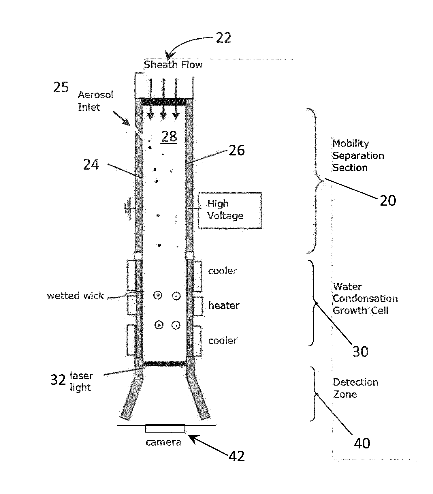
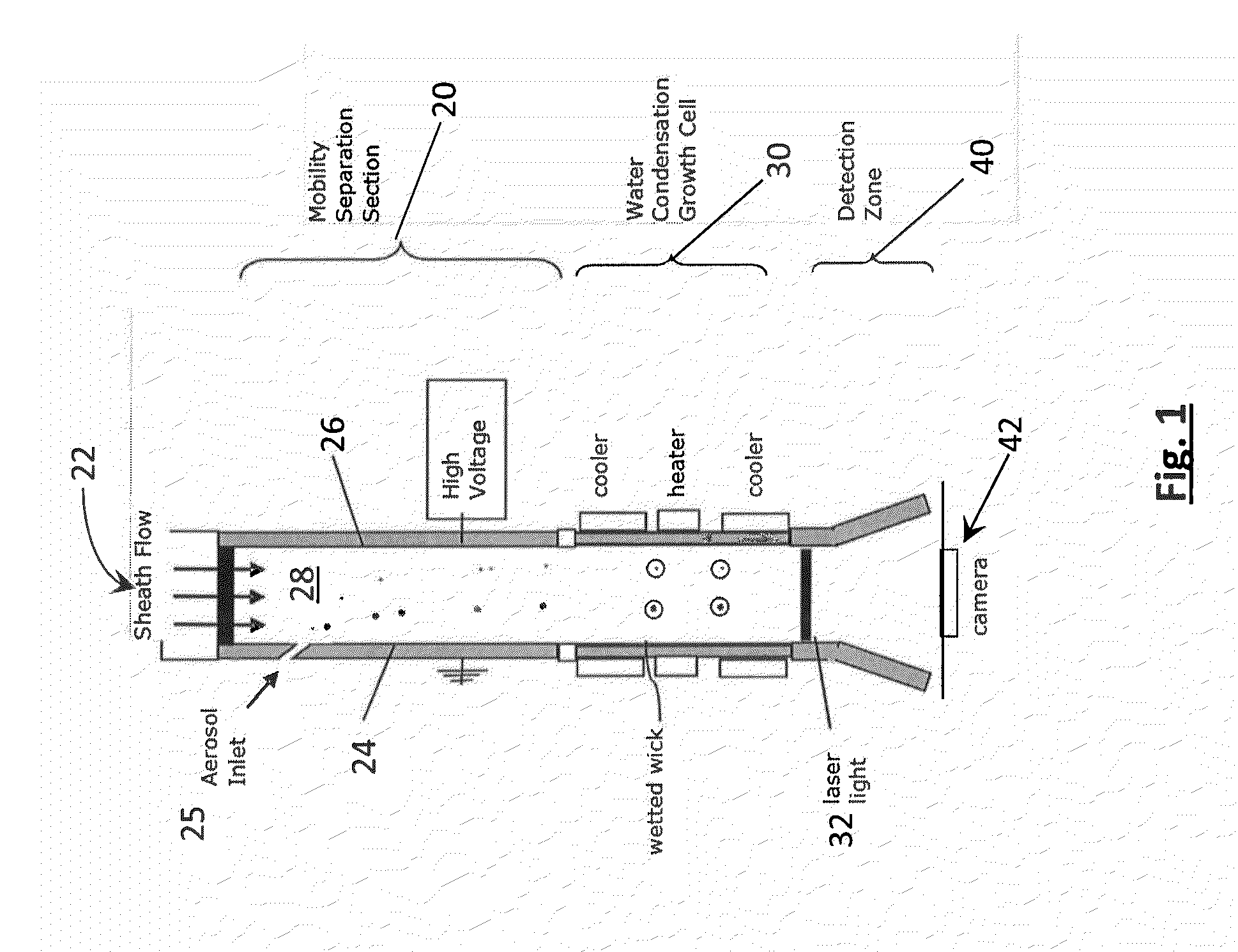
[0060]FIG. 8 depicts components of the AMI system, generally 500, including the features of the growth cell 200 of the Describing the AMI system 500 in a flow-wise direction, particle-free air flow enters the system via sheath flow inlet 502 upstream of the separator 510 region. Air flow containing the particles to be measured enters through the aerosol inlet 529. This embodiment 500 includes a three-stage condensational growth cell 525, comprising conditioner section 520, initiator section 530, and equilibrator section 540. Before entering the system, the aerosol to be sampled is charge neutralized using a bipolar ion source, which puts a known charge distribution on the particles. This aerosol sample flow is evenly distributed via an inlet slit 525 across the grounded plate 524 of the separator 510, where the aerosol joins the Sheath flow which fills most of the gap 528. In one example, the sheath flow rate is within a range of about 10-20 L / min, while the aerosol flow is within ...


PUM

PropertyMeasurementUnit
porosityaaaaaaaaaa
particle diametersaaaaaaaaaa
diameteraaaaaaaaaa

Abstract

A parallel plate dimensional electrical mobility separator and laminar flow water condensation provide rapid, mobility-based particle sizing at concentrations typical of the remote atmosphere. Particles are separated spatially within the electrical mobility separator, enlarged through water condensation, and imaged onto a CCD array. The mobility separation distributes particles in accordance with their size. The condensation enlarges size-separated particles by water condensation while they are still within the gap of the mobility drift tube. Once enlarged the particles are illuminated by a laser. At a pre-selected frequency, typically 10 Hz, the position of all of the individual particles illuminated by the laser are captured by CCD camera. This instantly records the particle number concentration at each position. Because the position is directly related to the particle size (or mobility), the particle size spectra is derived from the images recorded by the CCD.

Description

CROSS-REFERENCE TO RELATED APPLICATIONS[0001]The instant application claims priority under 35 U.S.C. §119(e) of prior U.S. Provisional Patent Application Ser. No. 61 / 710,858, filed 8 Oct. 2012 under the same title and having the same inventive entity as the instant application. The complete disclosure of the prior application is hereby incorporated herein by this reference in its entirely for all purposes.STATEMENT REGARDING FEDERALLY SPONSORED RESEARCH[0002]This invention was made with government support under contract number DE-AC02-98CH10886 with the U.S. Department of Energy, and under Grant No. SC0006312 from the U.S. Department of Energy. The government has certain rights in the invention.BACKGROUND[0003]1. Technical Field[0004]The present disclosure relates to measuring the size and number concentration of airborne particles. Specifically, this disclosure relates to rapid measurement of the particle size spectra and concentration in the ultrafine and sub-micrometer size range...

Claims


Application Information

Patent Timeline
Patent Type & Authority Applications(United States)
IPC IPC(8): G01N1/28G01N33/00G01N33/18G01N21/17
CPCG01N1/28G01N33/18G01N33/0009G01N21/17G01N2015/0046G01N15/0227G01N15/0255G01N15/065
Inventor WANG, JIANHERING, SUSANNE VERASPIELMAN, STEVEN RUSSELKUANG, CHONGAI
Owner AEROSOL DYNAMICS INC
Why Eureka
Try Eureka