UHF RFID Reader with Improved Antenna System

a technology of rfid reader and antenna system, which is applied in the direction of subscriber station connection selection arrangement, indirect connection of subscriber station, sensing record carrier, etc., can solve the problem of inability to identify tags by rfid reader, inability to modulate backscattered signals, and increased tag identification rate, etc. problem, to achieve the effect of improving quality

Inactive Publication Date: 2015-09-24
TAGSYS
View PDF6 Cites 19 Cited by
  • Summary
  • Abstract
  • Description
  • Claims
  • Application Information

AI Technical Summary

Benefits of technology

[0017]In this case, this antenna system offers an alternative to a mechanical stirring system in order to achieve field stirring by feeding in turn each individual antenna port with RF power. The position and polarization diversity possess the advantage not to involve the use of

Problems solved by technology

One of the major problems facing RFID systems today is to increase the tag identification rates when a large number of tags are present in a small enclosure.
The main cause for missed tags is the coupling between adjacent tags.
As a consequence, the tag can not modulate the backscattered signal and can not be identified by the RFID reader.
In addition, RFID communications normally take place in multipath environments and could suffer from large signal fadings which also reduce the identification rate.
But most of the ti

Method used


Image

  • UHF RFID Reader with Improved Antenna System
  • UHF RFID Reader with Improved Antenna System
  • UHF RFID Reader with Improved Antenna System

Examples


Embodiment Construction

[0026]The exemplification set out herein illustrates a preferred embodiment of the invention, and such exemplification is not to be construed as limiting the scope of the invention in any manner.

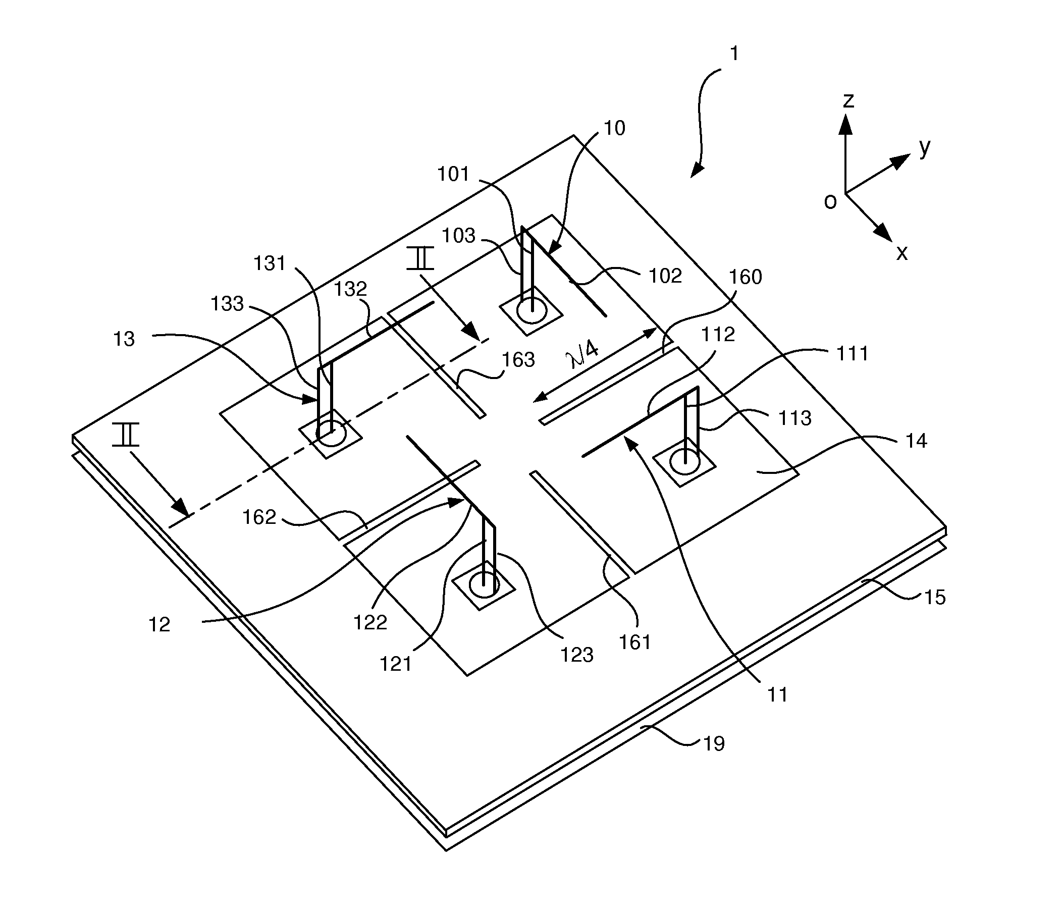
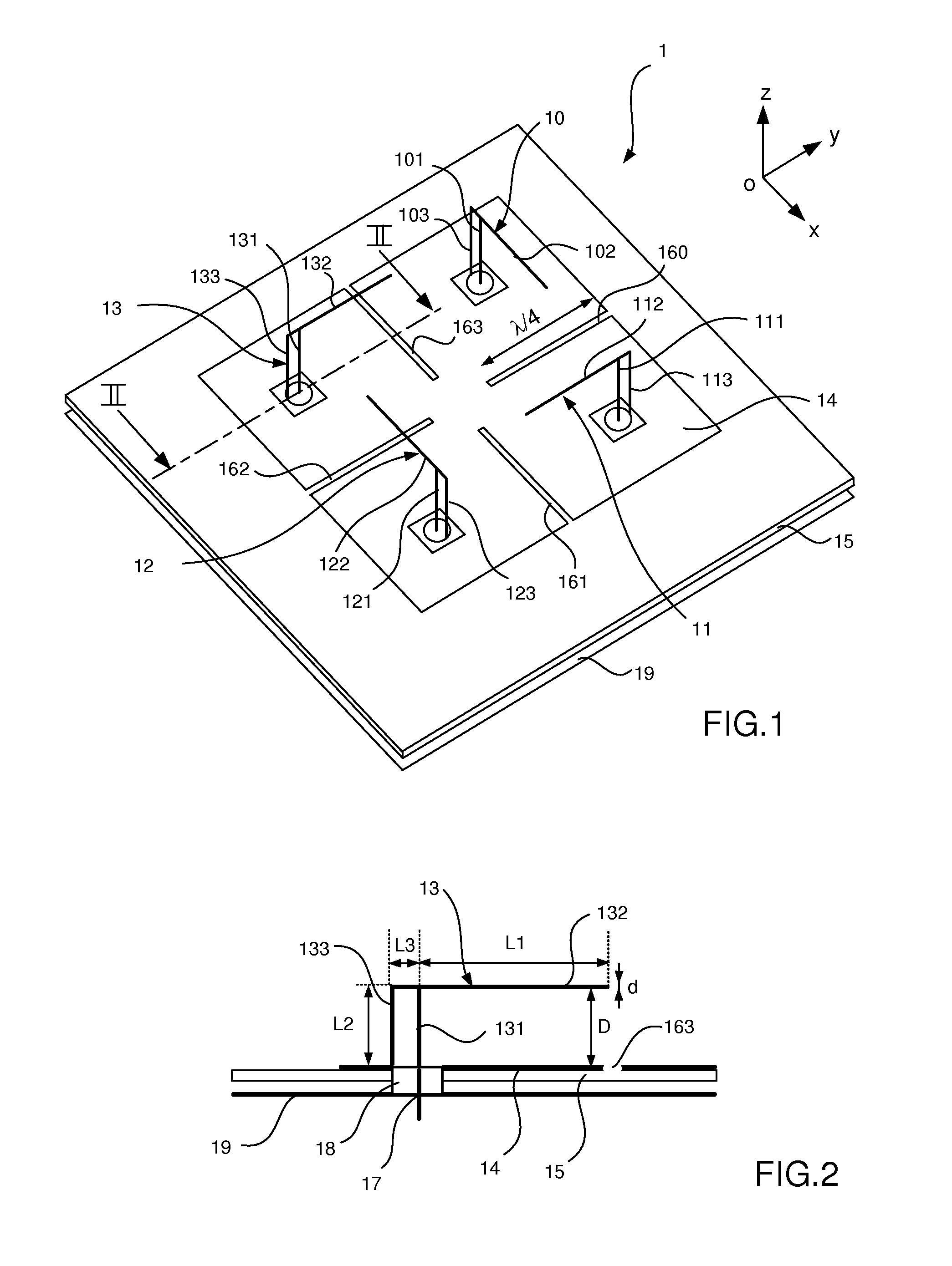
[0027]In the present specification, it is described an antenna system for RFID readers comprising 4 inverted F antennas (or IFAs) produced on a printed circuit board with a ground plane formed thereon, said IFAs being offset by a sequential rotation of 90°. This preferred embodiment is illustrated by FIGS. 1 and 2. FIG. 1 depicts the layout of this embodiment and FIG. 2 is a partial cross-section view of the antenna system of FIG. 1.

[0028]In reference to FIGS. 1 and 2, the antenna system 1 comprises 4 inverted F antennas (IFAs) 10, 11, 12 and 13 produced on a printed circuit board. Each IFA comprises a ground plane, a radiating element, a feed element and a shorting or tuning element. The ground plane, referenced 14, is formed on a substrate 15 of the printed circuit board. The ground plane ...


PUM


Abstract

The present invention relates to a RFID reader with an antenna system for emitting and receiving RFID signals. The antenna system includes at least a first inverted F antenna and a second inverted F antenna each having a feed element, a radiating element with a first end coupled to the feed element and a second end free, and a tuning element having a first end coupled to the ground plane and a second end coupled to the first end of the radiating element. The radiating elements of the two inverted F antenna extend in a first direction and a second direction respectively, said first and second directions being offset by a non-zero sequential rotation. In addition, the two inverted F antennas are isolated from each other by a quarter wavelength slot etched in the ground plane between the two antennas.

Description

TECHNICAL FIELD[0001]The present invention relates to RFID readers able to read RFID tags and more particularly to a RFID reader with improved antenna system.BACKGROUND OF THE INVENTION[0002]When UHF RFID technologies are used for logistics tracking / inventory control, it is usual to deal with a high density of tags, for instance to identify small items on pallets or shelves. One of the major problems facing RFID systems today is to increase the tag identification rates when a large number of tags are present in a small enclosure. The main cause for missed tags is the coupling between adjacent tags. Tag coupling yields what is sometimes called “masking”, but the antenna community rather visualizes it like a pattern distortion and a voltage drop at the antenna input. Under these conditions, the voltage at the chip input remains below a minimum voltage threshold. As a consequence, the tag can not modulate the backscattered signal and can not be identified by the RFID reader. In additio...

Claims


Application Information

Patent Timeline
IPC IPC(8): G06K7/10
CPCG06K7/10356G06K7/10346H01Q1/521H01Q21/28
Inventor POUSSOT, BENOITLAHEURTE, JEAN-MARCLOUSSERT, CHRISTOPHE
Owner TAGSYS
Why Eureka
Try Eureka