Printed active device

a printed active device and electronic component technology, applied in the field of manufacture of active electronic components, can solve the problems of reducing the production efficiency of electronic devices, and reducing the cost of manufacture. , the effect of reducing the overall weight of the articl

Active Publication Date: 2015-09-24
BRITISH TELECOMM PLC
View PDF8 Cites 33 Cited by
  • Summary
  • Abstract
  • Description
  • Claims
  • Application Information

AI Technical Summary

Benefits of technology

The present invention offers a method for producing three-dimensional objects with integrated electronic components through the use of additive manufacturing. By doing so, these objects may include sensors, actuators, and even complete functional units. This approach eliminates the necessity for separate parts and reduces costs while also allowing for protection against environmental factors. Electronic components can be placed anywhere throughout the object, making it easier to design and modify. Additionally, this technique enables the creation of truly smart objects with advanced functionality and potential recycling opportunities. Overall, this innovation expands the possibilities of what we can make using 3D printing technology.

Problems solved by technology

The problem addressed in this patent text is how to use additive manufacturing to make electronic devices without requiring post-manufacture assembly and installation. Current methods require accessibility for component location, sockets, and routes, losing the advantage of adding complexity to inner structures through accurate production. Additionally, these requirements increase manufacturing steps and costs while reducing efficiency.

Method used


Image

  • Printed active device
  • Printed active device
  • Printed active device

Examples


Embodiment Construction

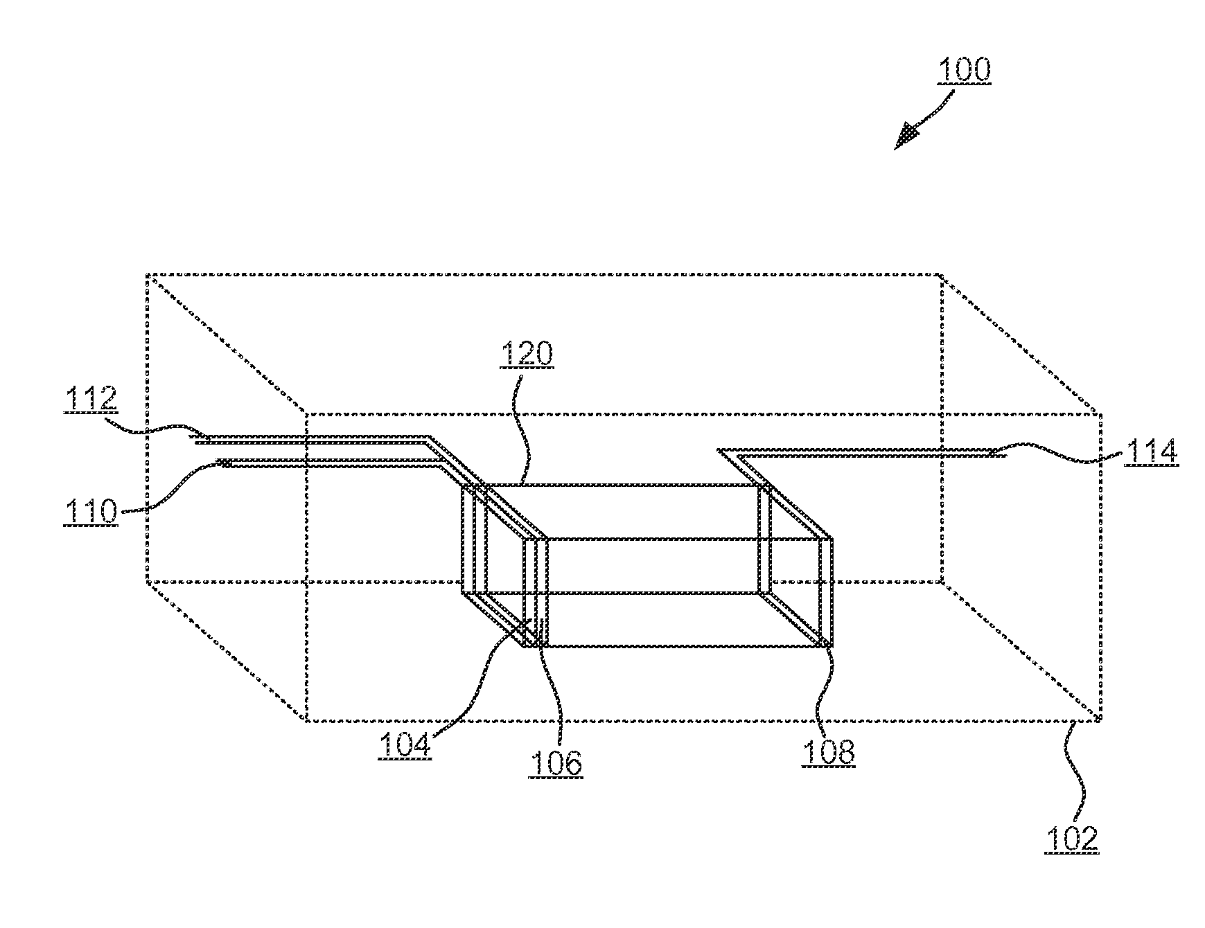
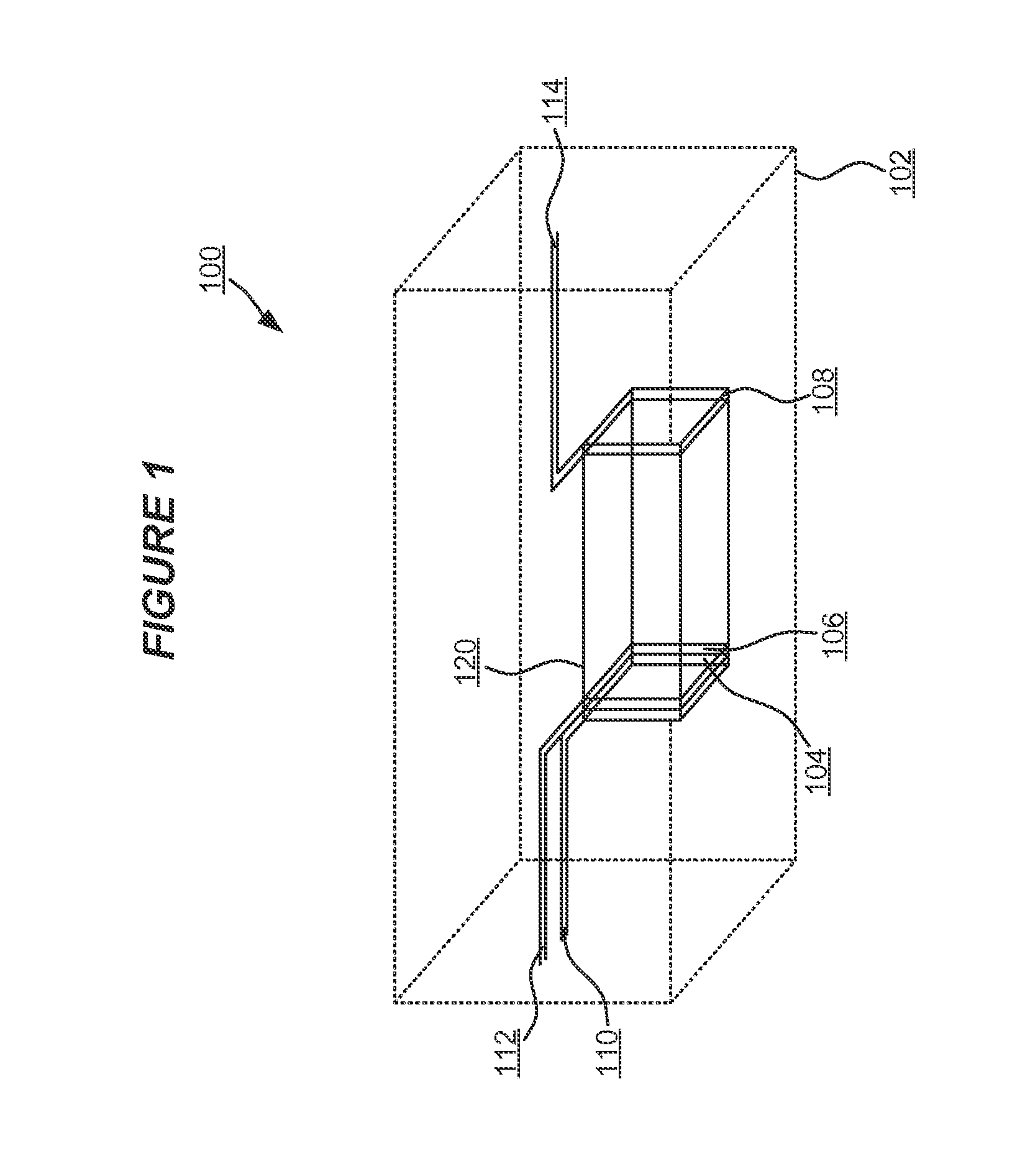
[0047]FIG. 1 depicts an exemplary three dimensional article 100 with integral diode 120 electronic component produced in accordance with embodiments of the present invention. The article 100 is constructed using an additive manufacturing approach including one or more techniques such as, inter alia: an extrusion deposition process; a material binding process such as selective laser sintering, direct metal laser sintering, selective laser melting or electron beam melting; and / or a stereolithographic approach such as photopolymerisation. Such techniques are also known as 3D printing, and a product or resulting article of such techniques is known as a 3D printed article or apparatus. The article 100 is comprised of a substantive structure 102 such as a body, framework, lattice, arrangement or other structure substantially constituting the article, otherwise referred to as the fabric of the article. For example, the article 100 can be, inter alia: a part; prototype; component; appliance...


PUM


Abstract

A method of manufacturing an article with integral active electronic component comprising: using an additive manufacturing process to: a) form a non-electrically conductive substrate; b) form a non-electrically conductive perforated layer having an aperture; c) form electrically conductive anode and cathode elements spaced in the aperture; d) deposit a conductive electrical connection to each of the elements suitable for imparting an electrical potential difference between the elements; e) form a non-electrically conductive sealing layer atop the perforated layer so as to retain and seal the aperture in the perforated layer.

Description


Claims


Application Information

Patent Timeline
Owner BRITISH TELECOMM PLC
Why Eureka
Try Eureka