Magnetic badminton racket and magnetic shuttlecock

Inactive Publication Date: 2015-10-01
SZE KA SHUN
View PDF0 Cites 2 Cited by
  • Summary
  • Abstract
  • Description
  • Claims
  • Application Information

AI Technical Summary

Benefits of technology

[0019]According to the present invention, the magnetic badminton racket has a simple structure and possesses strong magnetic attraction. The magnets in the racket are not subject to detaching from the racket and would not affect the aesthetic appearance of the racket. The alloy steel ring of the present shuttlecock has relative strong strength, and is not subject to deformation and damage. Besides, the resilience of the elastic cork would not be affected. Furt

Problems solved by technology

However, since a cork of a shuttlecock is not elastic enough to enable the shuttlecock to bounce after falling down to the floor, the players need to bend down frequently to pick up the shuttlecock, which may make them feel tired.
However, in the above-mentioned conventional magnetic badminton racket 40, the magnets 47 are provided at a top part of an outer ring of the head frame 44 and are exposed therefrom, which is not aesthetic.
In addition, if the magnets 47 are moun

Method used


Image

  • Magnetic badminton racket and magnetic shuttlecock
  • Magnetic badminton racket and magnetic shuttlecock
  • Magnetic badminton racket and magnetic shuttlecock

Examples


first embodiment

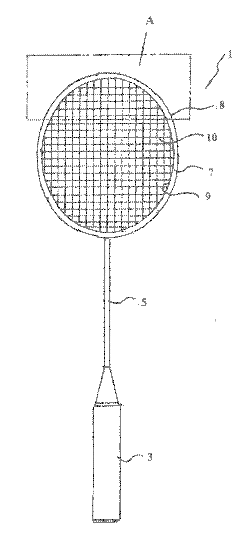
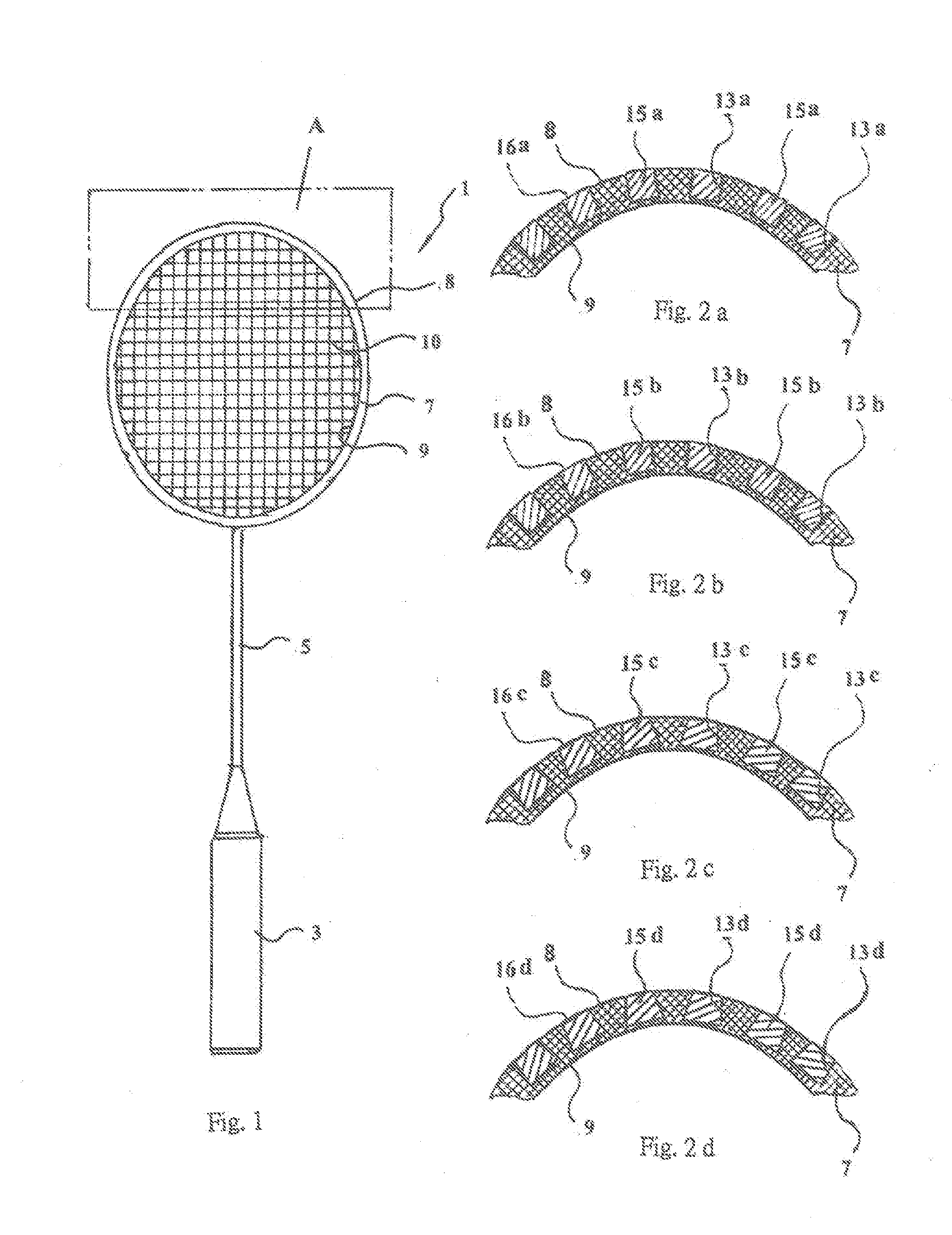
[0031]In the magnetic badminton racket of the present invention, as shown in FIGS. 1 and 2a, the magnetic badminton racket 1 comprises a handle 3, a shaft 5 connected to the handle 3, a head frame 7 connected to the shaft 5 and including an outer surface 8 and an inner surface 9, and a plurality of gut strings 10 crisscrossed within the inner surface 9 (the gut strings are omitted in FIG. 2a). The head frame 7 is provided with a magnet mounting section A centered on a top of the head frame, and the length of the magnet mounting section A is about ¼-⅓ of the peripheral of the head frame 7. Within the magnet mounting section A, a plurality of sockets 13a are provided into the outer surface 8, which are spaced from each other and vertical to the outer surface 8. A small neodymium magnet 15a is fixed within each socket 13a, and a top surface 16a of each small neodymium magnet 15a is exposed and flush with the outer surface 8. Each small neodymium magnet 15a is in the shape of a cylinder...

second embodiment

[0033]As shown in FIG. 2b, in the present magnetic badminton racket, each of the small neodymium magnets 15b is in the shape of a cuboid and has a top surface 16b. Each small neodymium magnet has a cross section with a size of 4 mm×4 mm and a height of 5 mm. Each small neodymium magnet 15b has a shape matching with that of a corresponding socket 13b, to enable to be tightly fitted to the corresponding socket 13b.

third embodiment

[0034]As shown in FIG. 2c, in the present magnetic badminton racket, each of the small neodymium magnets 15c is in the shape of a truncated cone, and has a top surface 16c with a diameter of 4 mm, a bottom surface with a diameter of 6 mm and a height of 5 mm. Each small neodymium magnet 15c has a shape matching with that of a corresponding socket 13c, to enable to be tightly fitted to the corresponding socket 13c.


PUM


Abstract

The invention discloses a magnetic badminton racket comprising: a handle, a shaft, a head frame including an outer surface and an inner surface and a plurality of gut strings crisscrossed within the inner surface. The head frame is provided with a magnet mounting section centered on its top, and several sockets are provided into the outer surface, spaced from each other and vertical to the outer surface. Several small neodymium magnets are fixed within the sockets, with their top surfaces exposed and flush with the outer surface. Each magnet is in the shape of a cylinder, cuboid, truncated cone or truncated quadrangular pyramid, which possesses strong magnetic attraction, is not subject to detaching and would not affect the aesthetic appearance of the racket. The invention also discloses a shuttlecock suitable for use together with the racket, to enable to pick up shuttlecock conveniently by mean of magnetic attraction therebetween.

Description

CROSS-REFERENCE TO RELATED APPLICATIONS[0001]The application claims the priority benefits of Chinese Patent Application No.201410116593.8 filed on Mar. 26, 2014, the contents of which are hereby incorporated by reference in its entirety.FIELD OF THE INVENTION[0002]The present invention generally relates to sporting goods for ball games, and particularly to a kind of magnetic badminton racket and a kind of magnetic shuttlecock.BACKGROUND OF THE INVENTION[0003]Badminton is a kind of favorite ball game for most people. Sporting goods for badminton are very simple and this kind of ball game does not need a large scale sports field. However, since a cork of a shuttlecock is not elastic enough to enable the shuttlecock to bounce after falling down to the floor, the players need to bend down frequently to pick up the shuttlecock, which may make them feel tired. Thus, it is desirable to develop a kind of sporting goods for badminton which could make it easy to pick up shuttlecocks.[0004]A C...

Claims


Application Information

Patent Timeline
IPC IPC(8): A63B49/02A63B49/12A63B67/18A63B49/10
CPCA63B49/02A63B49/10A63B2209/08A63B67/18A63B49/12A63B47/02A63B2102/04A63B67/187A63B67/197
Inventor SZE, KA SHUNKULTARIKAC, CHINRANGKHAKUN
Owner SZE KA SHUN
Why Eureka
Try Eureka