Air vehicle, actuator assembly and associated method of manufacture

a technology for actuators and air vehicles, applied in the field of air vehicles, can solve the problems of disadvantageous affecting the performance of air vehicles, heavy, large and expensive, and the design of heavier actuation systems, and achieve the effects of improving the reaction load path, improving the stiffness, and improving the rate of deflection

Active Publication Date: 2015-10-01
THE BOEING CO
View PDF29 Cites 12 Cited by
  • Summary
  • Abstract
  • Description
  • Claims
  • Application Information

AI Technical Summary

Benefits of technology

[0005]An air vehicle, an actuator assembly and a method of manufacture are provided according to example embodiments of the present disclosure in order to provide for an aircraft structure and an integrated actuator design and assembly that has improved performance, e.g., stiffness, rates, deflection, etc., weight, size and cost, and is within the outer mold line of the air vehicle. In this regard, the air vehicle, actuator assembly and method of manufacture and build of an example embodiment provide a structurally more efficient integration by integrating the actuator housing, the transmission, if any, and, in some embodiments, the actuation mechanism (e.g., gears, linkages, joints, pivots, crank arms, etc.) into the airframe structure in contrast to the mechanical attachment of an actuator housing to the airframe at discrete attach points. The integrated actuator assembly of an example embodiment provides for improved reaction load paths since the entire aircraft structure is reacting out internal loads as well as improved stiffness characteristics and geometric efficiencies relative to the mechanical attachment of an actuator housing to the airframe at discrete attach points. In addition, the integrated actuator assembly of an example embodiment may be more compact and take up less space relative to the redundant structure, discrete attach points and access requirements of a conventional actuator assembly. This more weight efficient compact integrated design may enable smaller and thinner shapes which may provide space for other systems or fuel as well as providing increased capabilities and performance. The benefits offered by embodiments of the air vehicle, actuator assembly and method of manufacture and build may lead to improved overall system performance, e.g., range, survivability, flight envelope, etc. since the outer mold line was not interrupted by the actuator assembly, more fuel may be carried, the aircraft weight may be reduced and / or the actuator assembly may be stiffer. Integrating the actuator assembly as part of the primary and secondary airframe structure will also enable innovative and more cost effective and efficient build and assembly approaches and processes.

Problems solved by technology

However, to meet system design, certification, and performance requirements, the design, build, attachment and installation of the actuator housing to the primary structure may be labor intensive, heavy, large and expensive.
Moreover, an actuator housing and mechanism that satisfies multiple system requirements, such as rate, loads, stiffness, deflection, etc., and is mechanically mounted to the primary or secondary structure may require altering the outer mold line of the air vehicle which, in turn, may disadvantageously affect the performance of the air vehicle.
In addition, a larger and heavier actuation system design also impacts the performance of the air vehicle and the space available for other aircraft systems and fuel.

Method used


Image

  • Air vehicle, actuator assembly and associated method of manufacture
  • Air vehicle, actuator assembly and associated method of manufacture
  • Air vehicle, actuator assembly and associated method of manufacture

Examples


Embodiment Construction

[0018]The present disclosure now will be described more fully hereinafter with reference to the accompanying drawings, in which some, but not all aspects are shown. Indeed, the disclosure may be embodied in many different forms and should not be construed as limited to the aspects set forth herein; rather, these aspects are provided so that this disclosure will satisfy applicable legal requirements. Like numbers refer to like elements throughout.

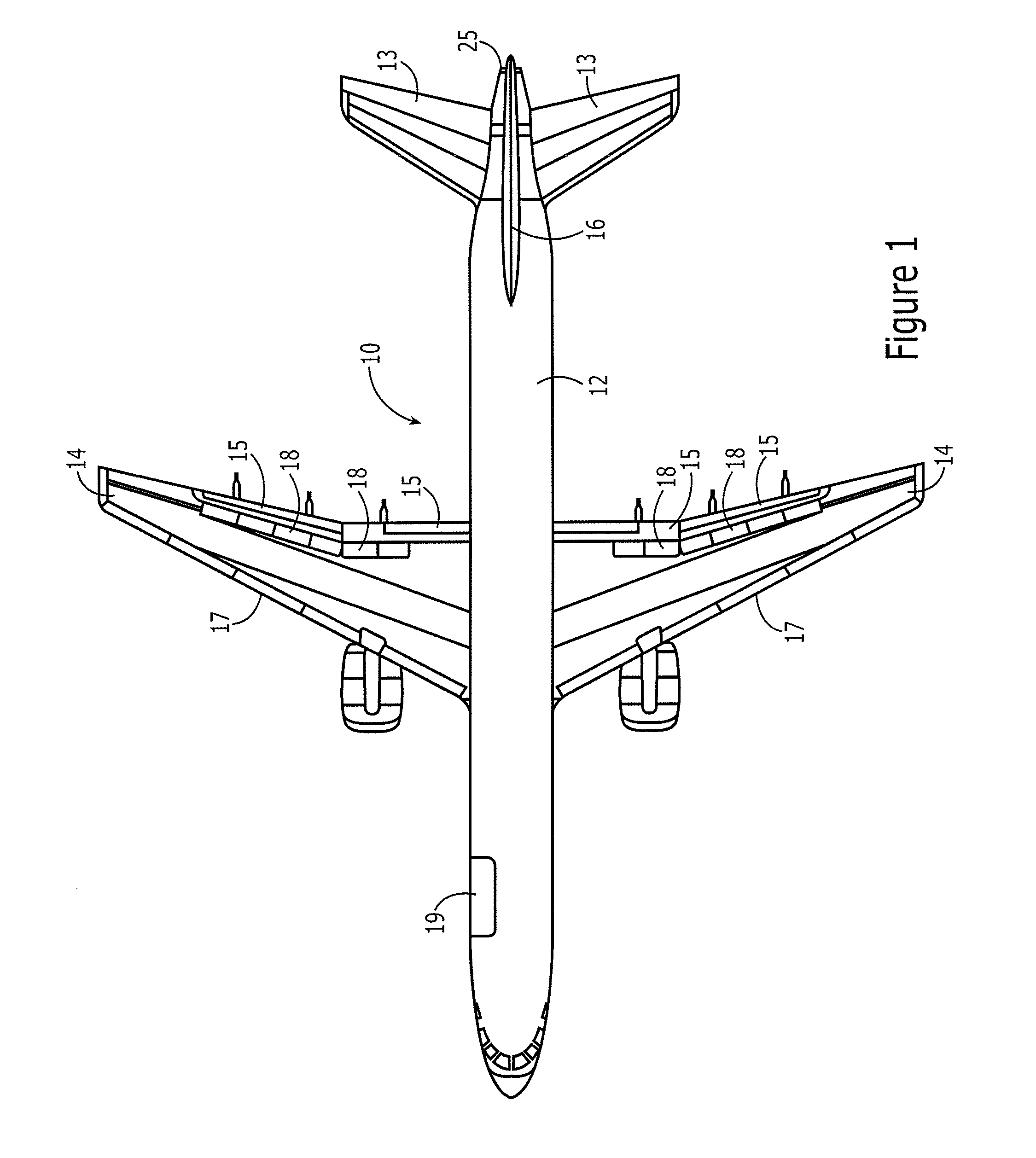
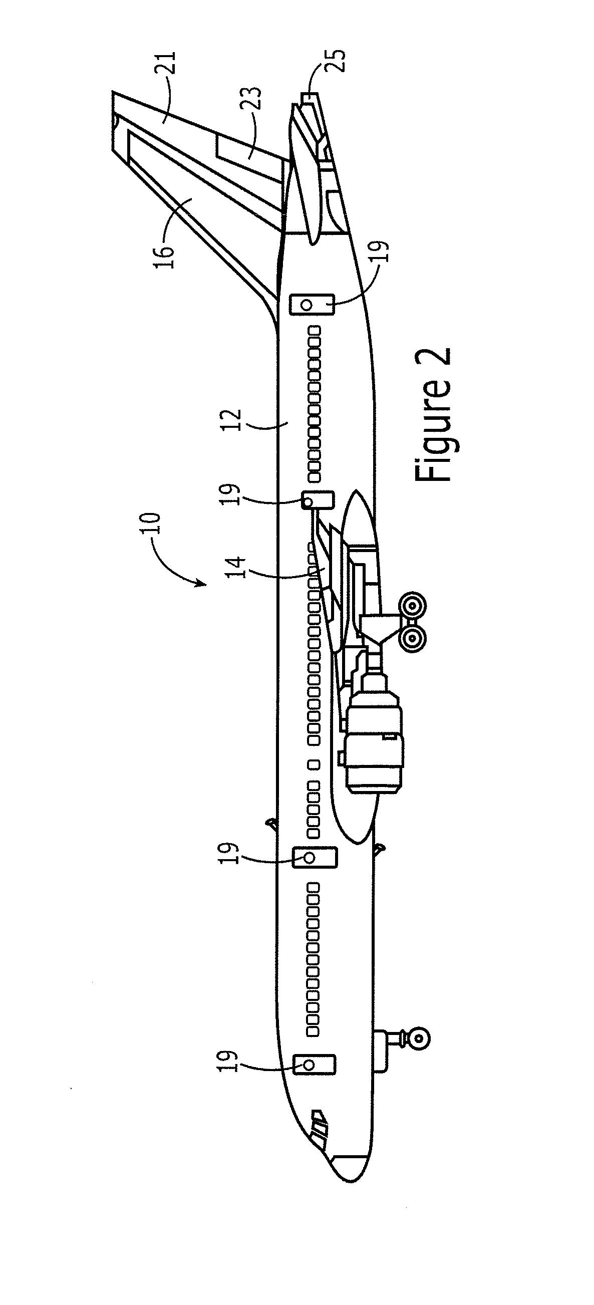
[0019]Referring now to FIGS. 1 and 2, an air vehicle 10 is depicted. The air vehicle of the illustrated embodiment is an aircraft. However, the air vehicle may be a different type of air vehicle, such as a spacecraft, rotorcraft, unmanned air vehicle, missile or other weapons, in other embodiments.

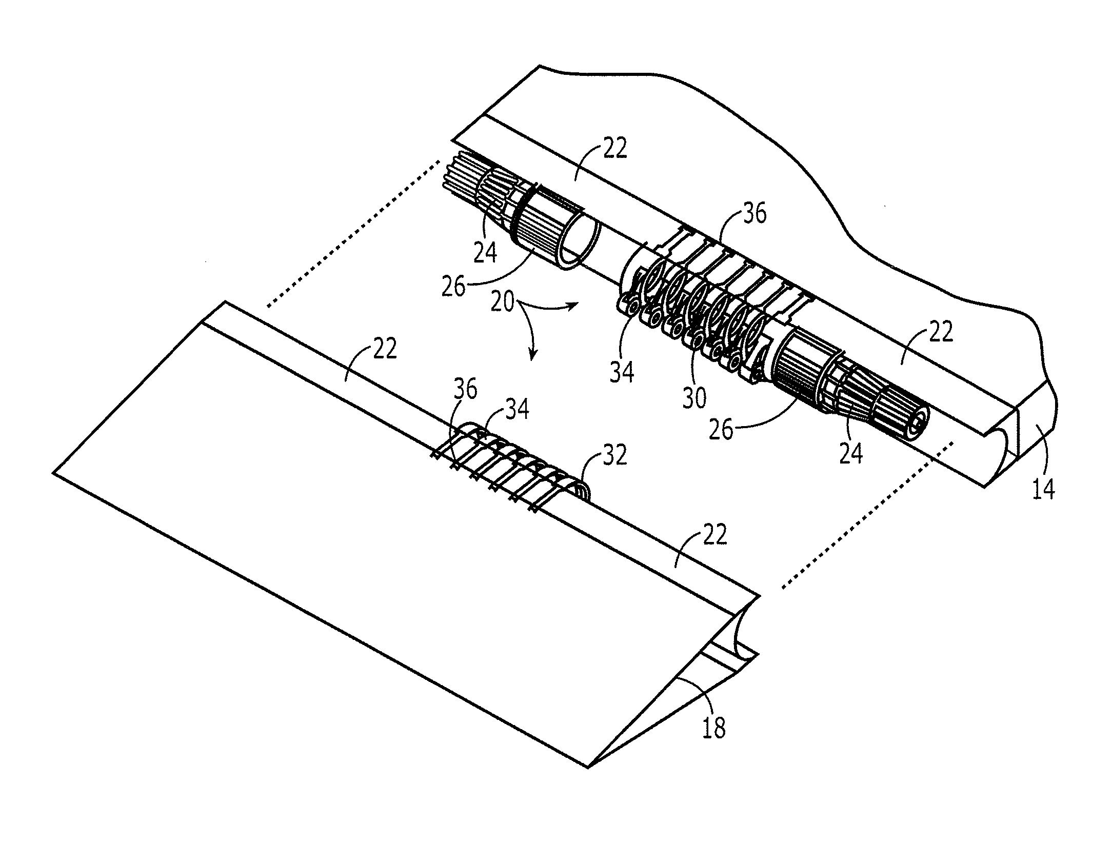
[0020]The air vehicle 10 includes a plurality of primary structures that are configured to remain in a fixed position relative to one another. Examples of primary structures include the airframe body, e.g., fuselage 12, the wings and wing tip 14, t...


PUM

PropertyMeasurementUnit
degrees of freedomaaaaaaaaaa
pressureaaaaaaaaaa
shapeaaaaaaaaaa

Abstract

An air vehicle, an actuator assembly and a method of manufacture are provided in order to incorporate the actuator assembly within the outer mold line of the air vehicle. In regards to an air vehicle, the air vehicle includes a primary structure and a movable structure configured to be controllably moved relative to the primary structure. The air vehicle also includes an actuator assembly configured to cause the movable structure to be positioned relative to the primary structure. The actuator assembly includes an actuator housing and an actuation mechanism. The actuation mechanism is at least partially disposed within the actuator housing and is configured to provide for relative movement between the primary structure and the movable structure. At least a portion of the actuator assembly is built into at least one of the primary structure and the movable structure so as to be within an outer mold line of the air vehicle.

Description

TECHNOLOGICAL FIELD[0001]An example embodiment of the present disclosure relates generally to an air vehicle that includes an actuator assembly and, more particularly, an air vehicle that includes an actuator assembly built into at least one of a primary structure and a movable structure so as to provide for controlled positioning of the movable structure relative to the primary structure.BACKGROUND[0002]Air vehicles, such as aircraft, rotorcraft, weapon, spacecraft or the like, often include a plurality of movable structures, such as control surfaces or other structures that are configured to be controllably moved and repositioned. For example, an aircraft may include a plurality of control surfaces that may be individually repositioned in order to perform controlled maneuvers to maintain the flight of the aircraft and / or to improve performance, such as by improving lift and lift trim, flow control, aircraft level flight trim, aircraft passive and active stability or internal volum...

Claims


Application Information

Patent Timeline
Patent Type & Authority Applications(United States)
IPC IPC(8): B64C13/34B64C13/26B64C9/00
CPCB64C13/34B64C13/26B64C9/00B64C9/02B64C13/38Y10T29/49826Y02T50/30Y02T50/40
Inventor SHEAHAN, JR., JAMES JOSEPHDROUIN, JR., DONALD V.
Owner THE BOEING CO
Why Eureka
Try Eureka