Eyewear lens production by multi-layer additive techniques

a technology of additive manufacturing and eyewear, applied in the field of eyewear lens production, can solve the problems of time-consuming process, less accurate correction, and computer-controlled surface equipment that allows more complex (e.g., multifocal) or individualized prescriptions to be prepared

Active Publication Date: 2015-10-01
INDIZEN OPTICAL TECH
View PDF3 Cites 38 Cited by
  • Summary
  • Abstract
  • Description
  • Claims
  • Application Information

AI Technical Summary

Benefits of technology

[0021]In a preferred embodiment, the angle and position of the lens substrate relative to the radiation-polymerizable material can be controlled while the liquid layer is applied. In a preferred embodiment, the lens substrate is moving with respect to the radiation-polymerizable material as the material is applied. In a further preferred embodiment, the lens substrate moves in at least one direction chosen from Y-translation, Z-translation and angle α rotation while the radiation-polymerizable material is applied. In another preferred embodiment, the lens substrate is moving at a non-perpendicular angle with respect to the radiation-polymerizable material being applied. In another preferred embodiment the angle, speed and / or direction of movement of the lens substrate varies while the radiation-polymerizable material is applied.

Problems solved by technology

This can be a time-consuming process.
However, finished lenses typically only approximate prescriptions in 0.25 D increments of sphere and cylinder corrections and therefore may be less accurate for correction.
Digital surfacing often requires only a limited number of semi-finished lens blanks or other starting lens constructs, but the computer-controlled surfacing equipment allows more complex (e.g., multifocal) or individualized prescriptions to be prepared.
This method can involve significant expenses in equipment and trained personnel.
In such processes, there is often a significant amount of waste material that must be safely handled, stored and eliminated.
While additive-type processes for spectral filtering are well known in the thin-film deposition field, these techniques are not used to create optical power changes for the final lens.
Often these supports are flat platforms, which are not intrinsically suitable for prescription eyewear lenses.
However, some disadvantages of additive production hamper implementation of these techniques for eyewear lenses.
Precision placement and control of layers is costly and time-consuming.
Eyewear lenses require much more material than contact lenses or intraocular implants and therefore exacerbate these disadvantages.
Materials suitable for additive production of plastic parts or even materials suitable for small, thin, flexible contact lenses may not combine the necessary optical and structural properties required for eyewear lenses that will be mounted in eyeglass frames.

Method used


Image

  • Eyewear lens production by multi-layer additive techniques
  • Eyewear lens production by multi-layer additive techniques
  • Eyewear lens production by multi-layer additive techniques

Examples


example 1

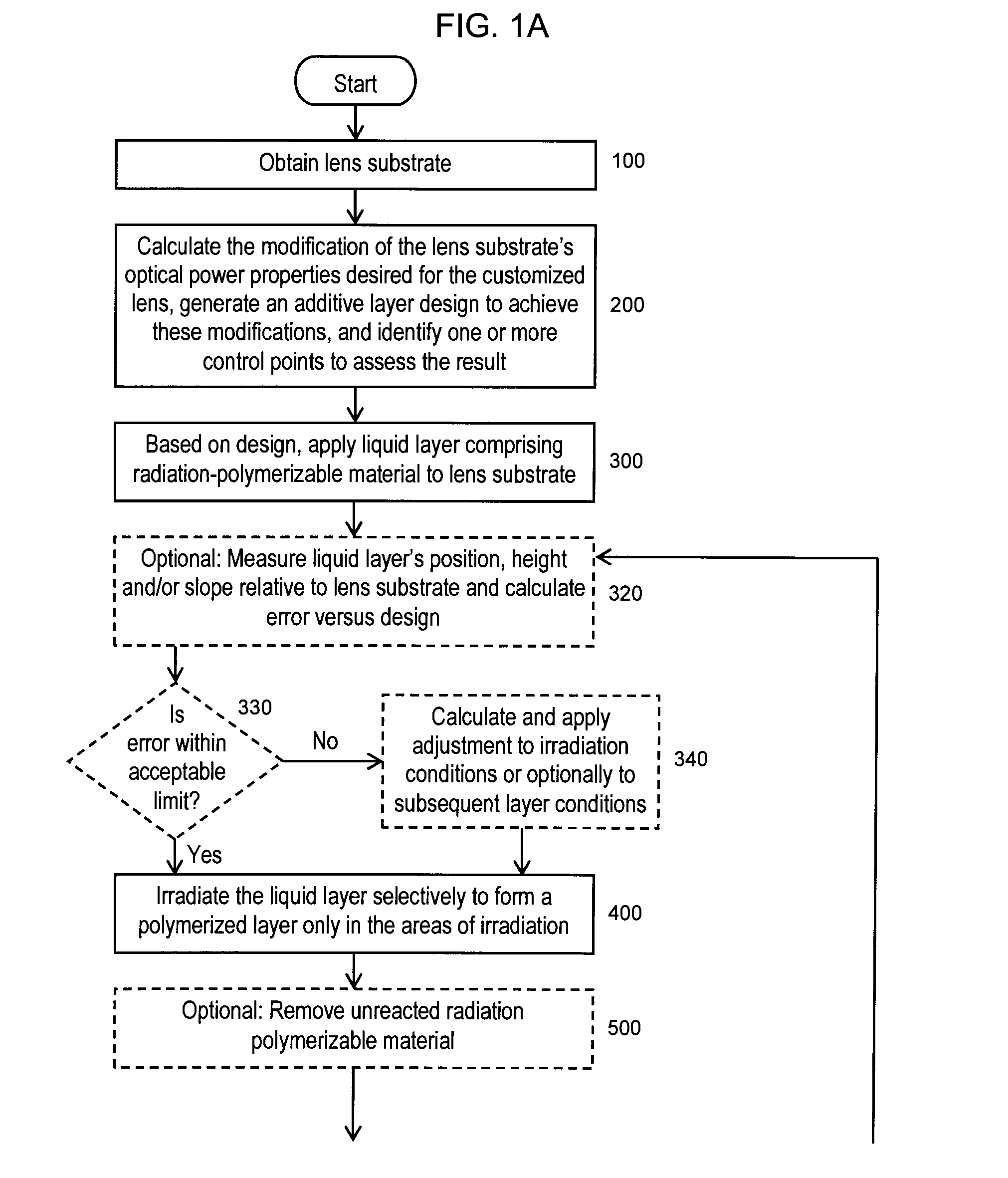
[0149]A plus powered finished lens substrate is held in a fixed mount such that the concave surface is exposed. (The concave surface of the lens substrate is the surface that will be nearest the eye when the customized lens is worn.) In this Example, an additive layer design is generated with successive additive layers of approximately 10 micrometers thickness each, comprised of one radiation-polymerizable material to be deposited on the concave surface of the lens substrate using a spray coating mechanism. The purpose of the additive layer design in this Example is to form a +2.00 Diopter added optical power region located on a portion of what will be the lower half of the customized eyewear lens when it is mounted in its frame. In this Example, if a lens substrate with refractive index of n=1.5 is used, and the additive layers comprise radiation-polymerized material that has a refractive index of 1.5, then 200 additive layers of approximately 10 micrometers thickness each will nee...

example 2

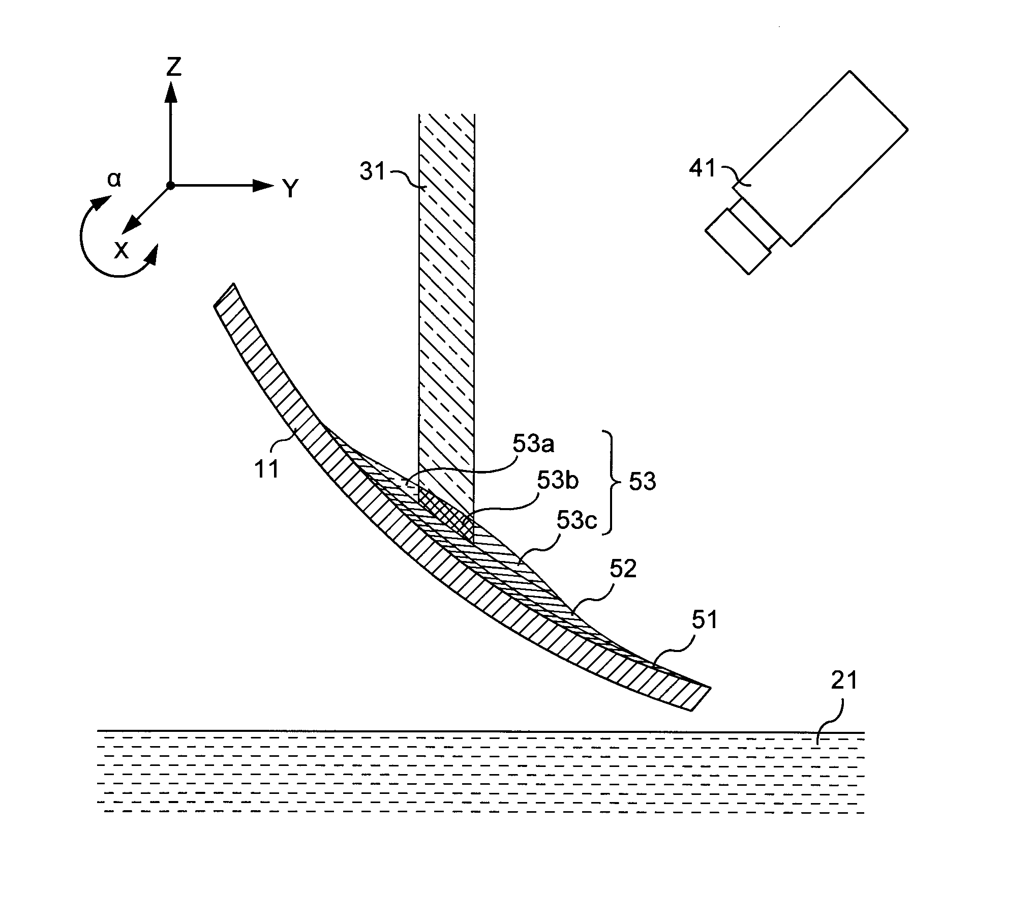
[0155]A finished plano lens substrate with a finished and polished convex surface is attached to a support mechanism such that the concave surface is exposed for the additive layer process in a configuration such as that illustrated in FIG. 2. The volume of the layers to be built on top of the initial substrate is computed as a series of successive layers with different thicknesses, such that each individual layer is no thicker than 100 micrometers at any point.

[0156]The blue light from an (R, G, B) projector is used to irradiate and selectively polymerize the liquid radiation-polymerizable material for the additive layer design. The red and green channels are specifically chosen to have wavelength distributions outside of the range that can cause reaction or polymerization of the material.

[0157]Before being attached to the support mechanism, the convex surface of the lens is covered with a plastic film (not shown in FIG. 2) that is opaque to the blue light being used for polymeriza...

example 3

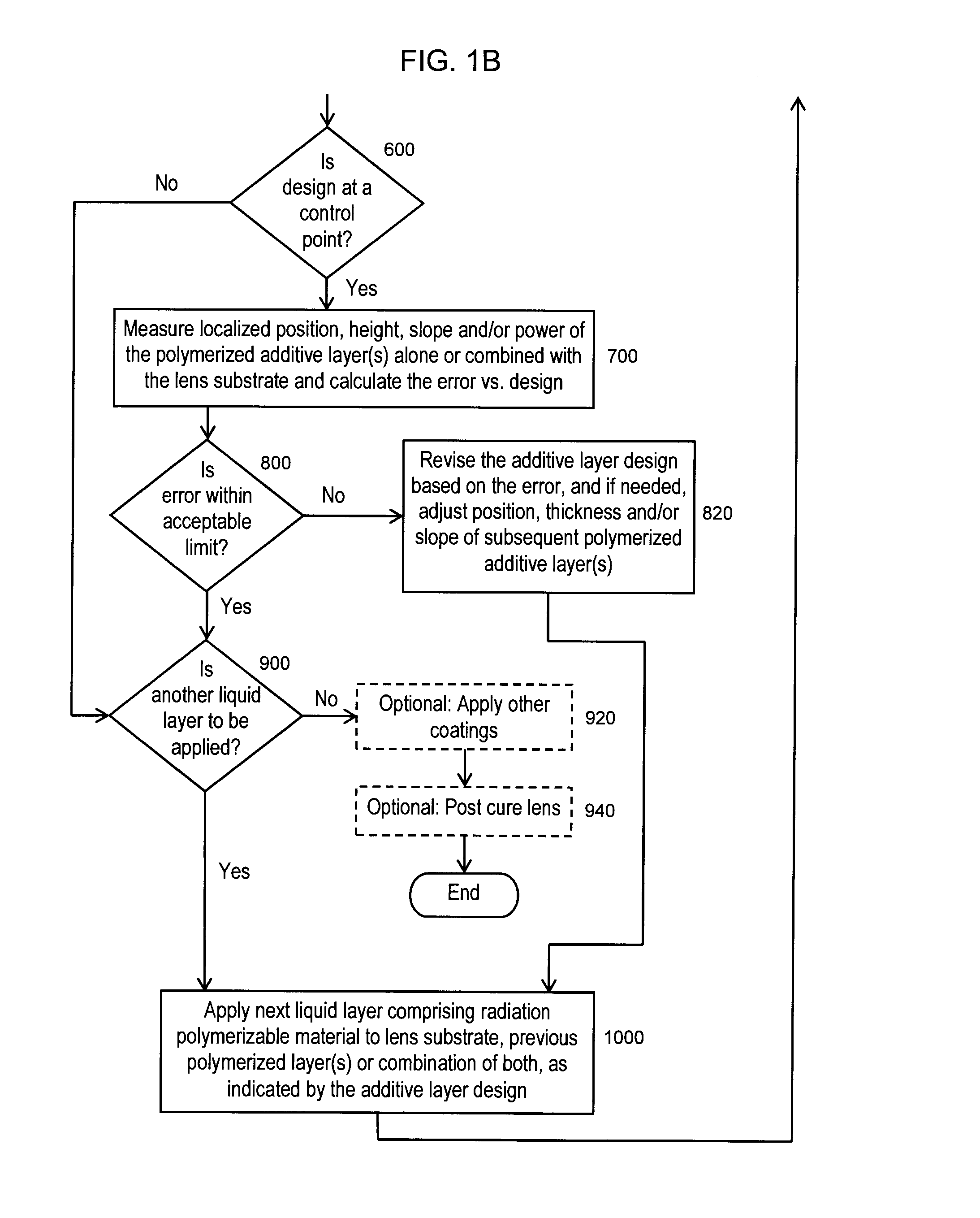
[0163]In another embodiment, the support mechanism and dipping method of EXAMPLE 2 is used with a different light source and measurement system. For EXAMPLE 3, an extended, structured light source like an LCD screen is used for irradiation. The camera and the extended light source measure the surface of the liquid close to the concave surface of the lens substrate by triangulation. In addition, the camera and extended light source is used to measure the shape of the polymerized additive layers for any errors, and the position, thickness or slope of the next layers of the additive layer design are adjusted based on the calculated errors.


PUM

PropertyMeasurementUnit
thicknessaaaaaaaaaa
thickaaaaaaaaaa
thickaaaaaaaaaa

Abstract

An additive processing method is used to produce a customized eyewear lens by selectively building layers of radiation-polymerized material onto a lens substrate that has optical power properties discernibly different from the optical properties of the customized eyewear lens. The method involves obtaining the lens substrate, calculating the modifications needed to convert the lens substrate's properties to the desired set of properties of the customized lens, generating an additive layer design to achieve the calculated modifications, and identifying at least one control point for confirmation or revision of the additive layer design. The method further involves applying liquid layers of radiation-polymerizable material to the lens substrate and irradiating the liquid layers in selected areas with controlled radiation such that the material is only polymerized and the additive layer is only formed in the select areas irradiated, according to the additive layer design.

Description

CROSS-REFERENCE TO RELATED APPLICATIONS[0001]None.FEDERALLY SPONSORED RESEARCH OR DEVELOPMENT[0002]Not applicable.JOINT RESEARCH AGREEMENT[0003]Not applicable.SEQUENCE LISTING[0004]Not applicable.BACKGROUND OF THE INVENTION[0005]1. Field of the Invention[0006]The field of the invention relates generally to methods of producing eyewear lenses, particularly spectacle lenses and lens blanks using additive techniques rather than removal of excess material.[0007]2. Description of Related Art[0008]Prescription eyewear lenses are commonly used to correct human vision errors, aberrations and focusing deficiencies caused by genetics, age, disease or other factors. In addition to correcting physiological vision problems, eyewear lenses may be used as a fashion accessory or to protect the eyes from hazards or discomfort.[0009]Prescription eyewear lenses must be prepared to meet each individual's specific vision requirements. Various techniques have been developed over the years to achieve this...

Claims


Application Information

Patent Timeline
Patent Type & Authority Applications(United States)
IPC IPC(8): G02B1/10G02B1/12G02C7/04G02B1/04
CPCG02B1/10G02C7/04G02B1/12G02B1/043B33Y80/00B29D11/00442B29D11/00951G02B27/0012G02C7/049B29L2011/0041B29C64/135B29D11/00961B29C64/268
Inventor MCKENZIE, ANDREW J.AMBLER, DAVID MARKVAZQUEZ, DANIEL CRESPOFERNANDEZ, JOSE ALONSOQUIROGA, JUAN ANTONIO
Owner INDIZEN OPTICAL TECH
Why Eureka
Try Eureka