
Electromagnetic skin treatment device

a skin treatment and electromagnetic technology, applied in the field of skin treatment devices, can solve the problems of affecting unable to cool down by internal air flow, and generating considerable heat, so as to achieve convenient integration, affect the efficiency of hair removal, and low absorbency

Active Publication Date: 2015-10-08
KONINKLJIJKE PHILIPS NV
View PDF11 Cites 36 Cited by
  • Summary
  • Abstract
  • Description
  • Claims
  • Application Information

AI Technical Summary

Benefits of technology

The invention is a handheld electromagnetic skin treatment device that can be used in a wet environment, such as a shower or bath. The device has a source of electromagnetic radiation, an energy supply, and a controller to control the supply of energy to the source. The device has an internal heat exchanger and an external heat exchanger, with a heat path from the internal to the external exchanger that passes through a watertight housing. This allows users to conveniently integrate the device with their hair removal or skin treatment activities in a shower or bath. The device also has safety detectors to prevent accidental exposure to light. The housing may also have one or more impermeable flexible inner liners for additional protection against water and shocks. The technical effects of this invention include improved cooling of the source, efficient skin treatment, and reduced pain and skin irritations.

Problems solved by technology

Use on wet skin or in combination with water is not believed to affect the efficiency of hair removal.
Cooling by an internal air flow would not be possible in the case of a watertight housing enclosing the source of electromagnetic radiation.
Due to the nature of such treatments, considerable heat is generated by the source of electromagnetic radiation and must be dissipated by heat exchange with the environment.

Method used


Image

  • Electromagnetic skin treatment device
  • Electromagnetic skin treatment device
  • Electromagnetic skin treatment device

Examples


first embodiment

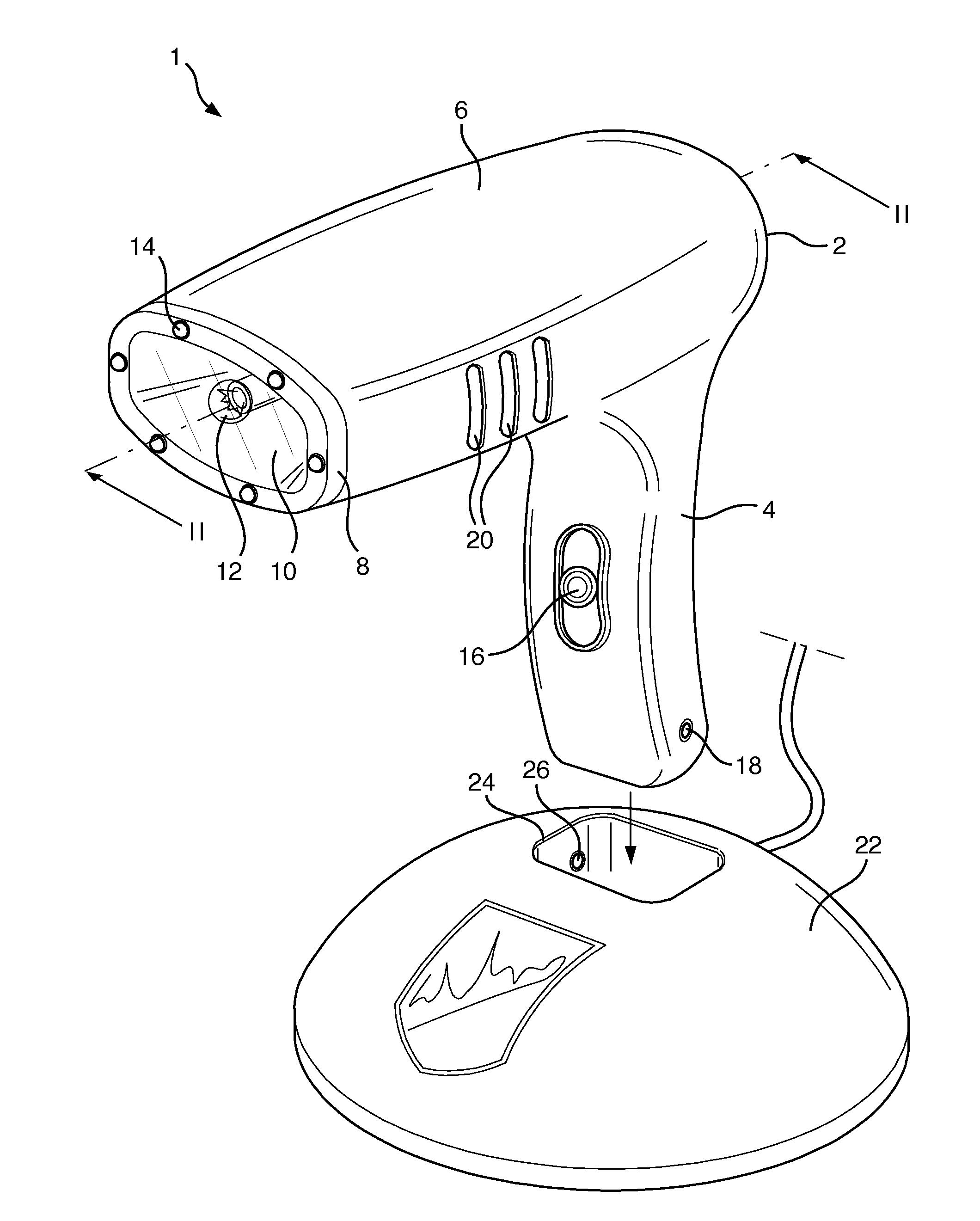
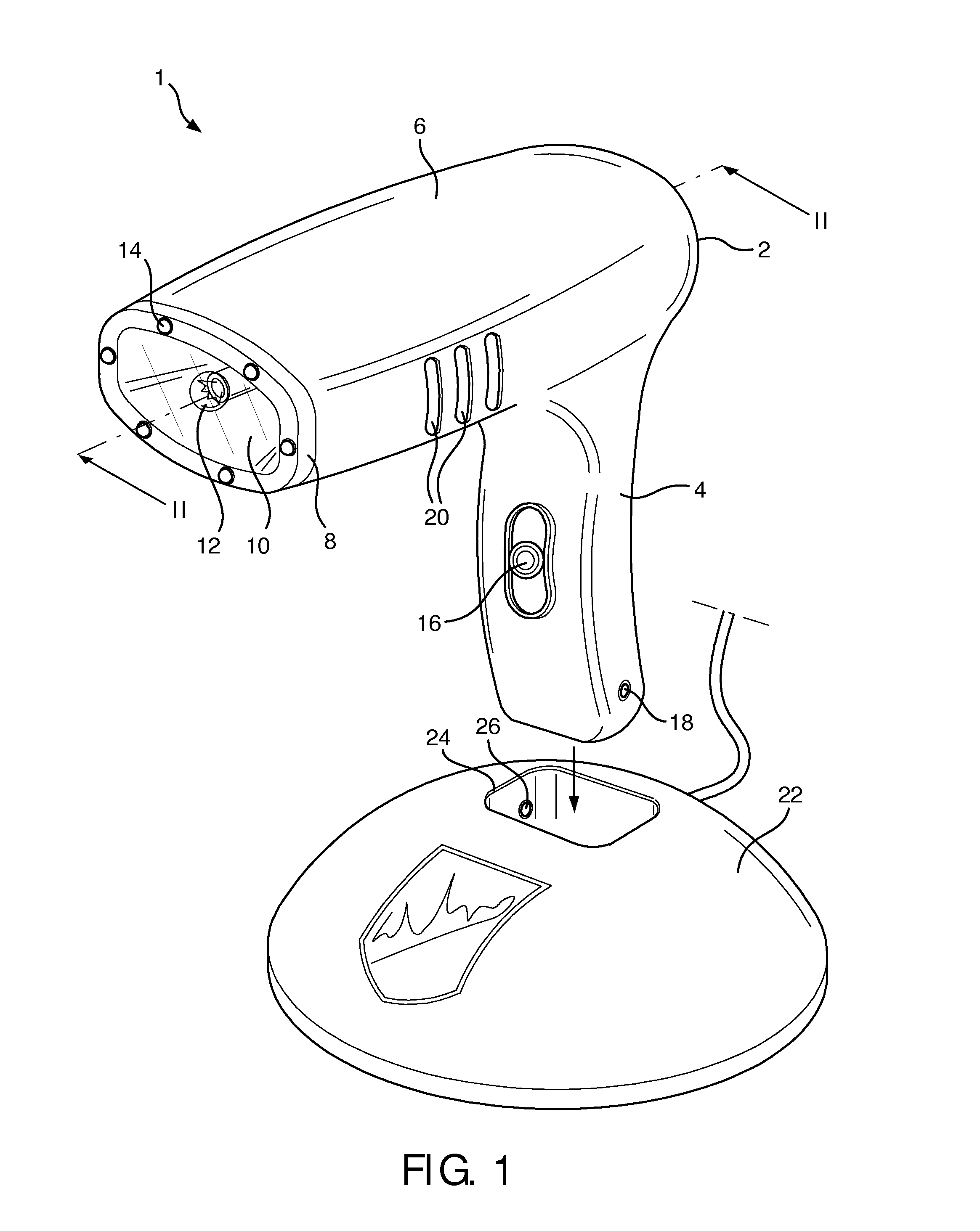
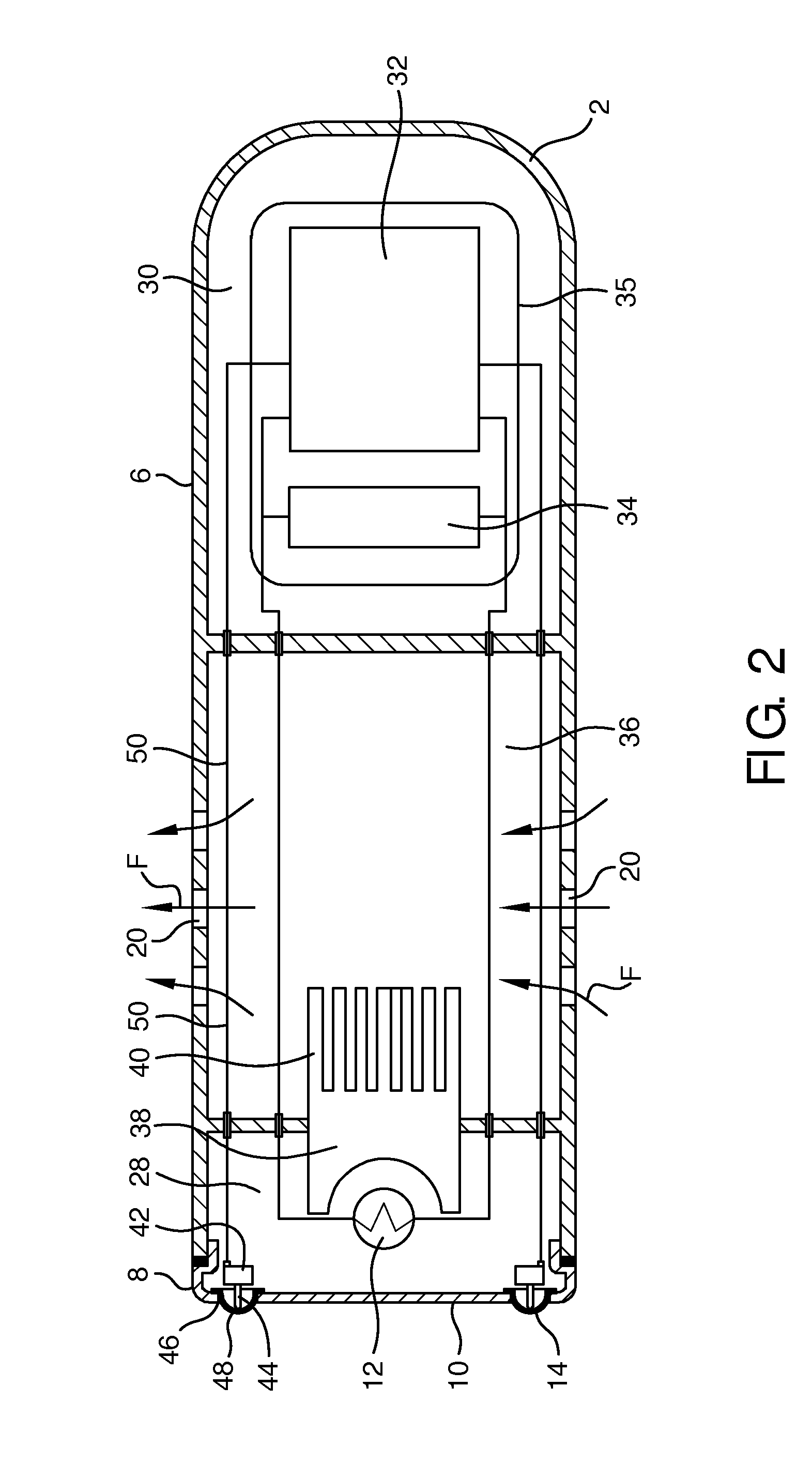
[0037]FIG. 1 shows a perspective view of an IPL hair removal device 1 according to the invention. Although the invention is further described only in the context of hair removal, it will be understood that it is equally applicable to other skin treatments. The device 1 comprises a watertight housing 2 having a handle portion 4 and a body portion 6. The body portion 6 terminates at a face plate 8 having a transparent window 10, behind which a xenon flash-lamp 12 is located. Safety detectors 14 are distributed around a circumference of the window 10, the purpose of which will be described hereinbelow. The handle portion 4 includes a trigger-like actuation switch 16 and electrical contacts 18, one of which is shown, for electrical recharging of the device. Passages 20 are formed in the body portion 6. Also shown in FIG. 1 is a charging station 22 by means of which the device 1 can be electrically recharged. The charging station 22 has a cradle 24 into which the handle portion 4 can be ...

second embodiment

[0041]the invention is shown in FIG. 3, which shows a hand-held hair removal device 101 in similar cross-section to FIG. 2. In this embodiment, like elements are denoted by similar reference numerals preceded by 100.

[0042]The device 101 of FIG. 3 differs from the first embodiment in that the watertight housing 102 comprises a single watertight compartment 128 without passages to the environment. In this embodiment, a heat sink 138, which forms an internal heat exchanger and which is located inside the watertight housing 102 in heat conducting relation with the flash-lamp 112, is connected via heat pipes 139 to cooling fins 140, which form an external heat exchanger located outside of the watertight housing 102 on an external surface of the watertight housing 102. The heat pipes 139 constitute a heat path from the internal to the external heat exchanger and may be generally of a conventional type and filled with a low-pressure cooling fluid. The heat pipes 139 each pass hermetically ...

third embodiment

[0043]the invention is shown in FIG. 4, which shows a hand-held hair removal device 201, also in similar cross-section to FIG. 2. In this embodiment, like elements are denoted by similar reference numerals preceded by 200.

[0044]The device 201 of FIG. 4 differs also from the first embodiment in that the watertight housing 202 comprises a single watertight compartment 228 without passages. In this embodiment, a heat sink 238, which forms an internal heat exchanger and is located inside the watertight housing 202 in heat conducting relation with the flash-lamp 212, is connected via heat conductors 239 to cooling fins 240, which form an external heat exchanger located on an external surface of the watertight housing 202. The heat conductors 239 constitute a heat path from the internal to the external heat exchanger and pass hermetically through walls of the watertight housing 202. In order to improve heat transfer, in addition to the conductors 239 the heat path comprises Peltier elemen...


PUM


Abstract

A hand-held skin treatment device comprises a source of electromagnetic radiation, an energy supply electrically coupled to the source and a controller arranged to control the energy supplied to the source of electromagnetic radiation. The source, the energy supply and the controller are enclosed in a watertight housing allowing use of the hand-held skin treatment device in a wet environment. To provide sufficient cooling of the source, the device comprises an internal heat exchanger in heat conducting relation with the source, an external heat exchanger outside of the watertight housing, and a heat path from the internal heat exchanger to the external heat exchanger that passes hermetically through a wall of the watertight housing. With this device, users can conveniently integrate their skin treatment activities with the daily washing routine in a shower or bath. The device is especially useful in the context of hair removal.

Description

BACKGROUND OF THE INVENTION[0001]1. Field of the Invention[0002]The present invention relates to skin treatment devices for application of electromagnetic radiation to the skin, and in particular to hand-held devices that can be used in a wet environment. The invention is for example applicable for removal of hair by application of localised energy to destroy or damage the hair follicle or root, thereby preventing re-growth.[0003]2. Description of the Related Art[0004]Light-based skin treatment devices are increasingly used for various forms of personal care and therapeutic treatments. Such treatments can include hair removal, skin rejuvenation, acne treatment, pigmentation removal and the like. In addition to treatment in the visible spectrum, other regions of the electromagnetic spectrum are also used, including the infra-red, ultraviolet and radio frequencies. Hereinafter, reference to light is not intended to be limited to the visible spectrum unless otherwise specified.[0005]Ha...

Claims


Application Information

Patent Timeline
IPC IPC(8): A61B18/18
CPCA61B18/18A61B2018/00023A61B2018/00047A61B2018/1807A61B2018/0047A61N2005/005A61N2005/0644F04C2270/0421
Inventor KINDERMANN, SEBASTIAN ALEXANDERSLADECEK, MARCELMIKULA, CHRISTIAN
Owner KONINKLJIJKE PHILIPS NV
Learn More