Load Distribution Management for Groups of Motorized Lifting Devices

a technology of load distribution and motorized lifting, which is applied in the field of hoists and winches, can solve the problems of preventing the use of applications, the inability of other hoists and winches to be economically viable for use in applications, and the inability to accurately and precisely control the load of some hoists and winches in certain applications, so as to reduce the gear ratio of the motor and prevent the rotation of the drum

Active Publication Date: 2015-10-08
HALL LABS LLC
View PDF80 Cites 17 Cited by
  • Summary
  • Abstract
  • Description
  • Claims
  • Application Information

AI Technical Summary

Benefits of technology

[0014]In a third embodiment of the invention, an apparatus includes a drum to draw in or let out a line and a motor and transmission coupled to the drum to apply a torque thereto. The transmission includes at least one stage of gearing to reduce a gear ratio of the motor relative to the drum. A shaft couples the motor to the transmission and a locking mechanism selectively locks the shaft to prevent rotation of the drum. In certain embodiments, a braking mechanism may be provided in addition to the locking mechanism to slow the motor when the motor is not applying torque to the drum. This may slow the motor sufficiently to enable engagement of the locking mechanism.

Problems solved by technology

For example, some hoists or winches are bulky or cumbersome, which may prevent their use in applications where greater compactness is required or desired.
Other hoists and winches may be economically infeasible for use in applications such as consumer or residential applications due to their complexity or expense.
The accuracy and precision of some hoists and winches may also be lacking in certain applications.
The result is that, for any given angle of rotation of the spool, an unpredictable amount of line may be drawn in or let out.
This can make the hoist or winch unsuitable for applications where a high degree of precision is required.
It can also make the winch or hoist unsuitable for operations that require a high degree of repeatability.
For example, current hoists and winches may lack mechanisms for determining certain parameters during operation.
For example, short of manually measuring or observing a hoist or winch, it may be difficult or impossible to determine how much line is let out from the hoist or winch at any given time.
Even if possible, it may not be possible to do so with a desired degree of precision.
In other cases, the ability to determine a load on the hoist or winch, or adjust the speed of a hoist or winch (which may depend on the load) may be lacking.
In yet other cases, an event such as a power outage or reset may cause a hoist or winch to forget or lose information regarding current operating parameters.
This may slow the motor sufficiently to enable engagement of the locking mechanism.

Method used


Image

  • Load Distribution Management for Groups of Motorized Lifting Devices
  • Load Distribution Management for Groups of Motorized Lifting Devices
  • Load Distribution Management for Groups of Motorized Lifting Devices

Examples


Embodiment Construction

[0071]It will be readily understood that the components of the present invention, as generally described and illustrated in the Figures herein, may be arranged and designed in a wide variety of different configurations. Thus, the following more detailed description of the embodiments of the invention, as represented in the Figures, is not intended to limit the scope of the invention, as claimed, but is merely representative of certain examples of presently contemplated embodiments in accordance with the invention. The presently described embodiments will be best understood by reference to the drawings, wherein like parts are designated by like numerals throughout.

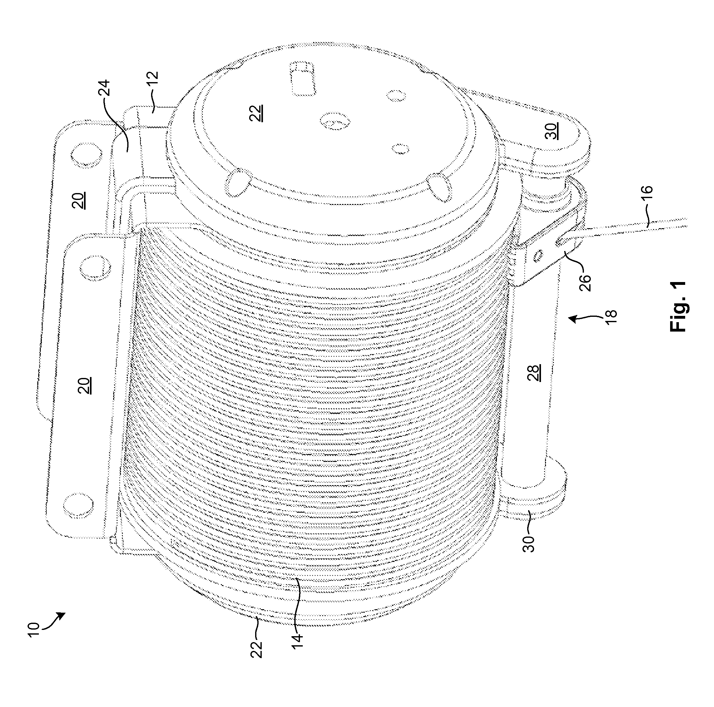
[0072]Referring to FIG. 1, a perspective view showing one embodiment of a motorized lifting device 10 in accordance with the invention is illustrated. Although the motorized lifting device 10 is described herein primarily as it relates to lifting objects, the device 10 may also be used to pull loads in the manner of convent...


PUM


Abstract

A system includes multiple lifting devices, where each lifting device includes a drum to draw in or let out a line, and a motor and transmission coupled to the drum to apply a torque thereto. A grouping module groups the lifting devices for synchronized operation in lifting a shared load. A load distribution management module monitors an amount of weight carried by each of the grouped lifting devices and provides feedback to a user to enable more optimal distribution of the shared load amongst the grouped lifting devices.

Description

RELATED APPLICATIONS[0001]This application claims priority to U.S. Provisional patent Ser. No. 61 / 822,644 filed on May 13, 2013 and entitled “A Winch System Comprising Insulated Cables”; U.S. Provisional patent Ser. No. 61 / 924,157 filed on Jan. 6, 2014 and entitled “Cable Guide”; U.S. Provisional patent Ser. No. 61 / 925,144 filed on Jan. 8, 2014 and entitled “Smart Lift”; U.S. Provisional patent Ser. No. 61 / 925,182 filed on Jan. 8, 2014 and entitled “Smart Multi Lift”; and U.S. Provisional patent Ser. No. 61 / 933,508 filed on Jan. 30, 2014 and entitled “Lift Platform”.[0002]This application is a continuation of U.S. patent application Ser. No. 14 / 245,308 filed on Apr. 4, 2014 and entitled “Accurate Position Tracking for Motorized Lifting Device”; which is a continuation of U.S. patent application Ser. No. 14 / 245,234 filed on Apr. 4, 2014 and entitled “Intelligent Motorized Lifting Device”; which is a continuation of U.S. patent application Ser. No. 14 / 245,132 filed on Apr. 4, 2014 and...

Claims


Application Information

Patent Timeline
Patent Type & Authority Applications(United States)
IPC IPC(8): B66D1/48B66F7/28B66D1/58B66D1/26B66F7/02
CPCB66D1/48B66D1/26B66F7/28B66D1/58B66F7/02B66D1/22B66D1/38B66D1/485B66C13/16G01G19/14G01G19/18G01G23/18B66C13/46G01G9/00G01G23/3728
Inventor HALL, DAVID R.MILES, JEROMEHYER, DAVIDOREES, KEVIN
Owner HALL LABS LLC
Why Eureka
Try Eureka