This helps you quickly interpret patents by identifying the three key elements:
Problems solved by technology
Method used
Benefits of technology
Benefits of technology
The invention provides a method of forming a stable membrane using amphipathic molecules between two polar volumes of a medium. The membrane is resistant to detergents and proteins, and can withstand larger potential differences in potential. The membrane can also contain a transmembrane pore for the characterization of target analytes. The invention also provides a system comprising two volumes of polar medium separated by an apolar medium, with a layer of amphipathic molecules around the surface of at least one of the polar volumes. The method and system can be used for the stable formation of membranes in various applications such as membrane separation and analyte characterization.
Problems solved by technology
However drawbacks that are sometimes associated with lipid bilayers include that they are not particularly robust and are prone to rupture, for example by digestion by enzymes, and are not able to withstand large potential differences.
Such a configuration, which is shown in FIG. 1 of U.S. Pat. No. 6,916,488, would not however seem suitable for stabilising aqueous droplets in oil.
Such ABA molecules do not therefore seem to be a viable alternative to the lipids described in WO2009 / 024775, for producing a droplet interface layer from a water-in-oil system.
Method used
Image
Click on the blue label to locate the original text in one second.
Reading with bidirectional positioning of images and text.
Examples
example 1
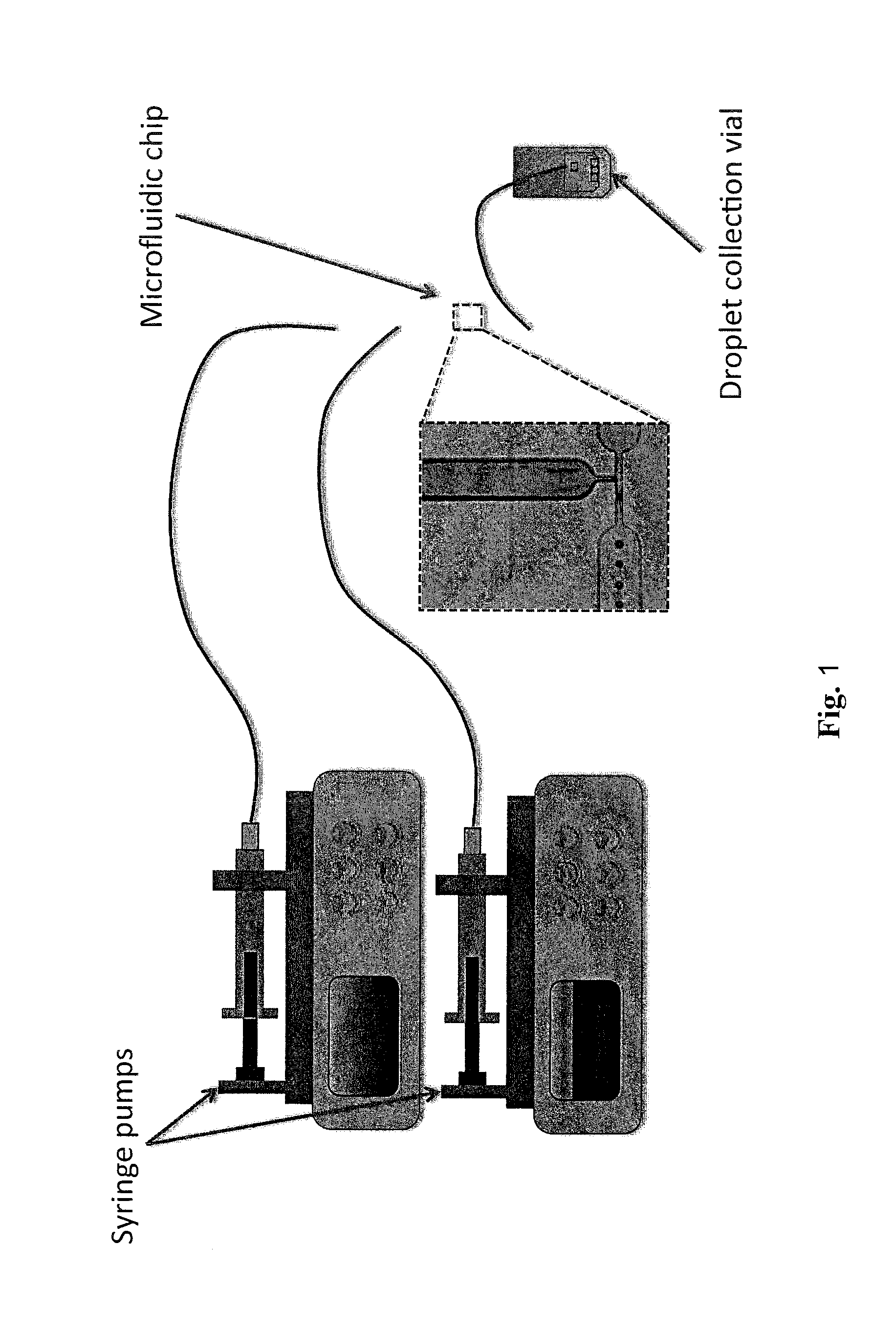
[0345]This example describes the method used to produce the triblock co-polymer droplets which are used to fill the interconnecting compartments on the microfluidic chips.
Materials and Methods
[0346]The T-junction chips are prepared for droplet generation by affixing nanoport assemblies (Upchurch Scientific) as fluidic interfaces.
[0347]The droplet generation mechanism in a T-junction is well documented in the literature [Garstecki et al., Lab Chip, 2006, 6, 437-446 and Thorsen et al., Physical Reviw Letters, 86, 18, 4163-4166]. Taking into account the fluid viscosities of the reagents involved the chosen T-junction geometry was 50 μm channel width for both cases (oil and buffer).
1.1—Droplet Reagents
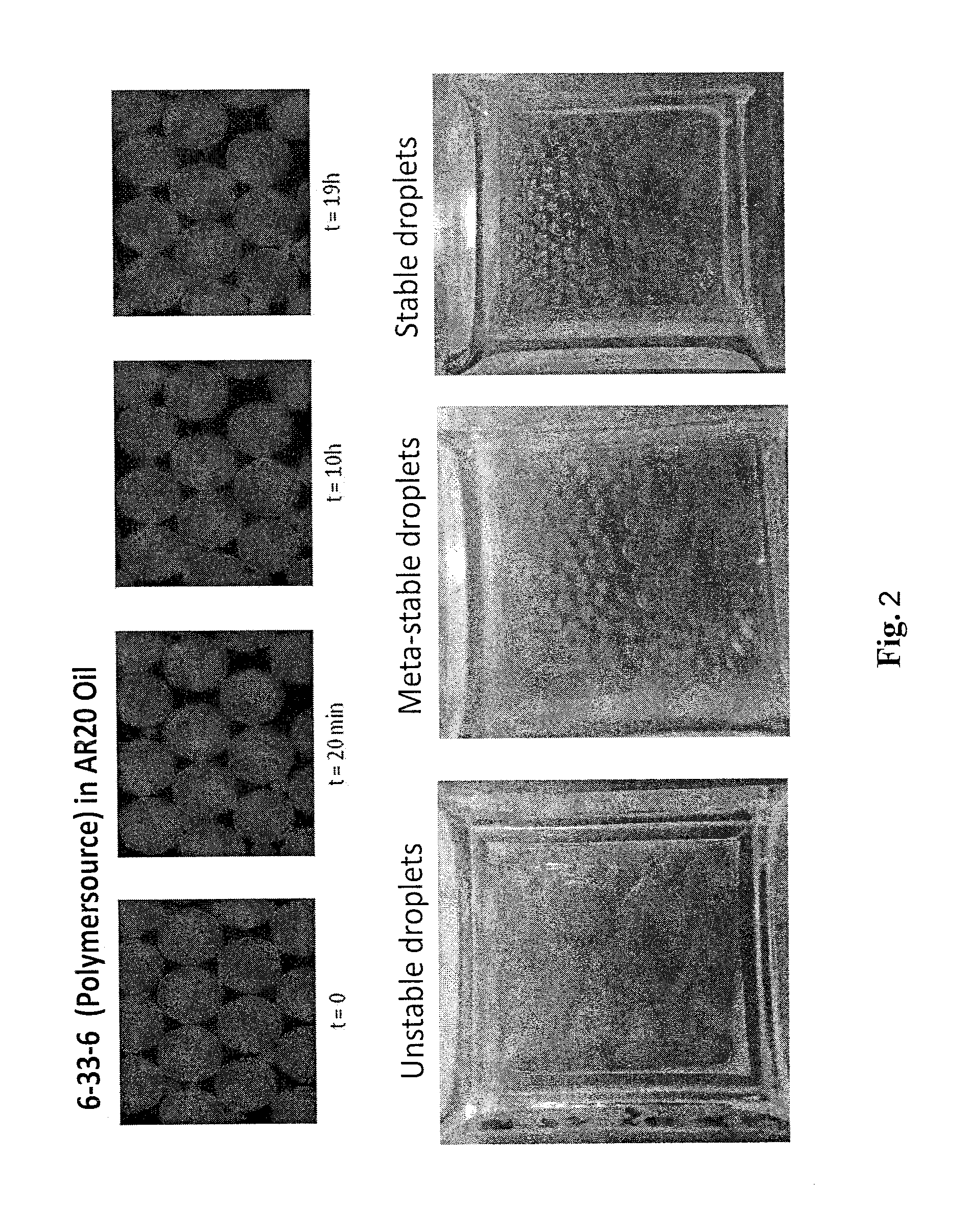
[0348]In order to make aqueous phase droplets in oil, buffer is used as the disperse phase, while a silicon oil (e.g. AR20), is used as the continuous phase. Both buffer and triblock co-polymer-containing oil are prepared as described below.
[0349]A solution of buffer (buffer 1) was prepare...
example 2
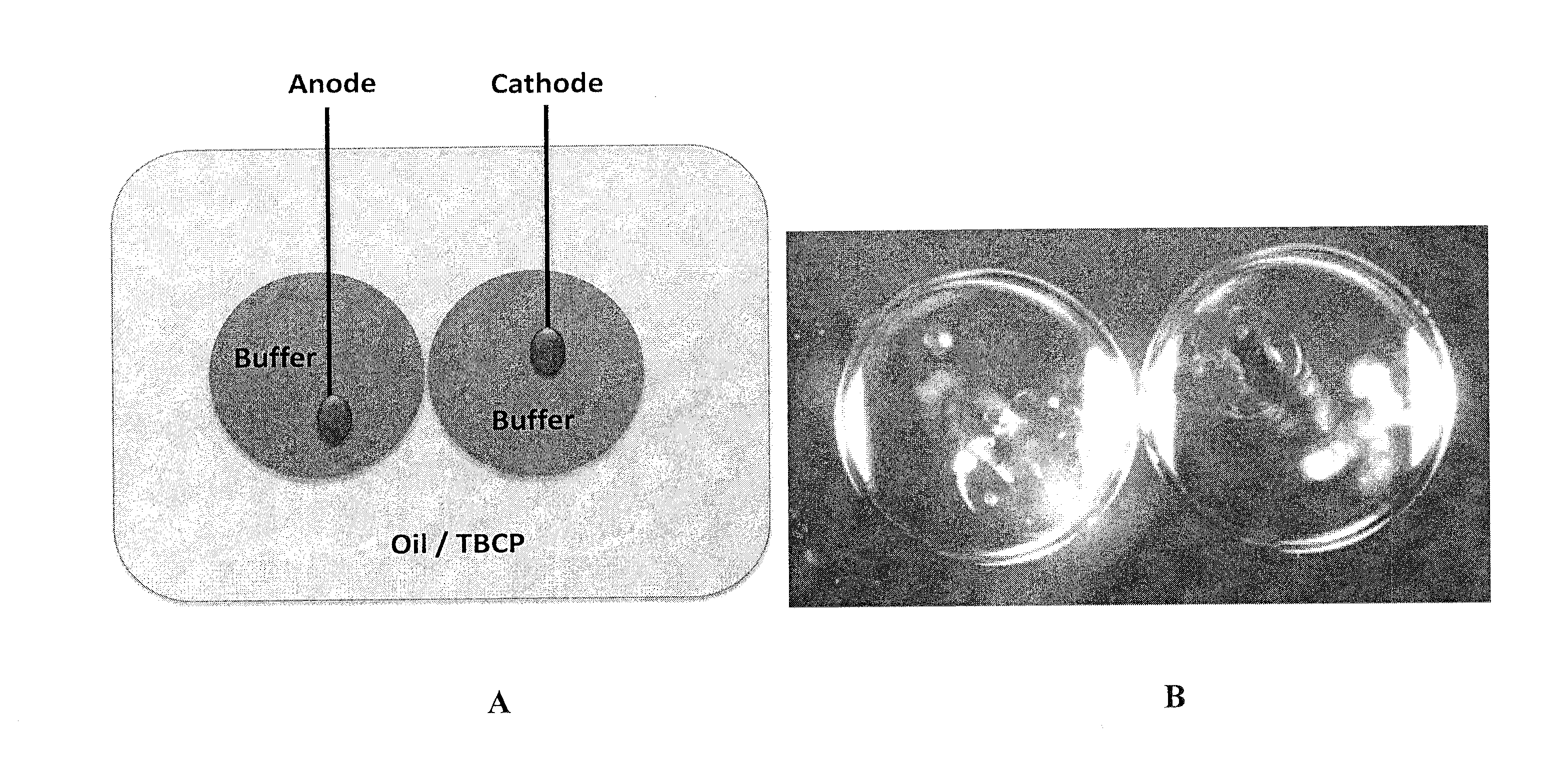
[0353]This example describes the method used to produce droplet-interface-bilayers (DIBs) using a number of different tri-block co-polymers in different oils (experimental set-up shown in FIG. 3). The ability to form bilayers and to allow insertion of biological nanopores (such as mutants of MspA) was also investigated.
Materials and Methods
[0354]Experiments 2.1, 2.3 and 2.4 were carried out on the below combinations of tri-block co-polymer and oil.
PUM
Property
Measurement
Unit
Fraction
aaaaa
aaaaa
Diameter
aaaaa
aaaaa
Diameter
aaaaa
aaaaa
Abstract
The invention provides a method of forming a membrane between a first volume of polar medium and a second volume of polar medium, which method comprises: (a) providing a first volume comprising polar medium and a second volume comprising polar medium which are separated from one another by an apolar medium, wherein at least one of said first and second volumes comprises a layer comprising amphipathic molecules, at the interface between the polar medium and the apolar medium, wherein each of the amphipathic molecules comprises a first outer hydrophilic group, a hydrophobic core group, and a second outer hydrophilic group, wherein each of the first and second outer hydrophilic groups is linked to the hydrophobic core group; and (b) causing the first and second volumes to come into contact with one another to form a membrane comprising said amphipathic molecules between the first and second volumes. The invention also provides a system comprising a membrane between a first volume of a polar medium; and a second volume of a polar medium, which membrane comprises the amphipathic molecules, and wherein the first volume of polar medium is within an apolar medium.
Description
FIELD OF THE INVENTION[0001]The invention relates to a membrane between first and second volumes of a polar medium. The invention also relates to a method of forming such a membrane.BACKGROUND TO THE INVENTION[0002]Lipid bilayers are thin polar membranes formed from two layers of lipid molecules. Lipid bilayers are found in cell membranes of most living organisms and are usually composed of phospholipids. They are impermeable to most hydrophilic molecules and ions, and enable cells to regulate their salt concentrations and pH by pumping ions across the lipid bilayer using transmembrane proteins known as ion pumps. Lipid bilayers, or more generally bilayers of amphipathic molecules, also serve as excellent platforms for a range of experimental studies. Holden et al, J. Am. Chem. Soc. 2007, 129, 8650-8655 disclose the formation of functional bionetworks of aqueous droplets comprising lipid bilayers provided between droplets. Such networks can act as light sensors, batteries and electr...
Claims
Application Information
Patent Timeline
Application Date:The date an application was filed.
Publication Date:The date a patent or application was officially published.
First Publication Date:The earliest publication date of a patent with the same application number.
Issue Date:Publication date of the patent grant document.
PCT Entry Date:The Entry date of PCT National Phase.
Estimated Expiry Date:The statutory expiry date of a patent right according to the Patent Law, and it is the longest term of protection that the patent right can achieve without the termination of the patent right due to other reasons(Term extension factor has been taken into account ).
Invalid Date:Actual expiry date is based on effective date or publication date of legal transaction data of invalid patent.

