Apparatus and methods for light beam routing in telecommunication

a technology of telecommunications and apparatus, applied in the direction of holographic light sources/light beam properties, holographic processes, instruments, etc., can solve the problems of difficult accurate rendition of pixel array patterns in liquid crystal, low crosstalk, and special problems of telecommunications holographic techniques, so as to achieve more rapid convergence of algorithms and increase the size of fields

Active Publication Date: 2015-10-08
CAMBRIDGE ENTERPRISE LTD
View PDF1 Cites 11 Cited by
  • Summary
  • Abstract
  • Description
  • Claims
  • Application Information

AI Technical Summary

Benefits of technology

[0025]In preferred embodiments the kinoform is also modified to redistribute the amplitude noise away from a desired position of the output beam in a replay field of the kinoform, for example b

Problems solved by technology

The use of holographic techniques, in particular kinoforms (phase only holograms) in telecommunications presents special problems, in particular because of the high signal-to-noise (SNR)/low crosstalk requirements as compared with display applications.
For example in a display application the level of noise/crosstalk may be of order 1:300 whereas in a telecommunications device it may be of order 1:10000. other special problems which can arise are as follows:Operation at the long wavelength of 1.5 micron necessitates the use of thick liquid layers (compared with visible light devices), making the a

Method used


Image

  • Apparatus and methods for light beam routing in telecommunication
  • Apparatus and methods for light beam routing in telecommunication
  • Apparatus and methods for light beam routing in telecommunication

Examples


example implementation

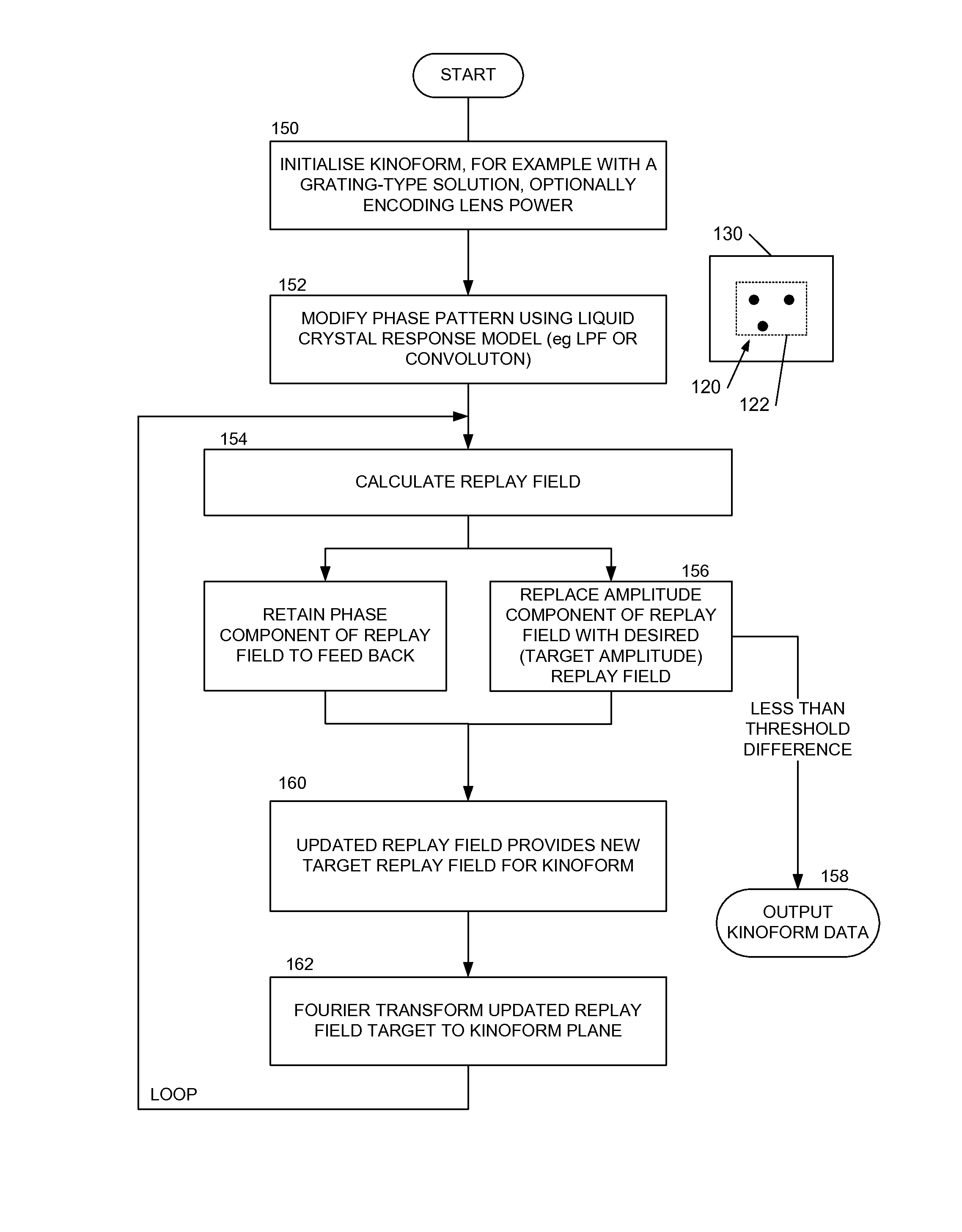
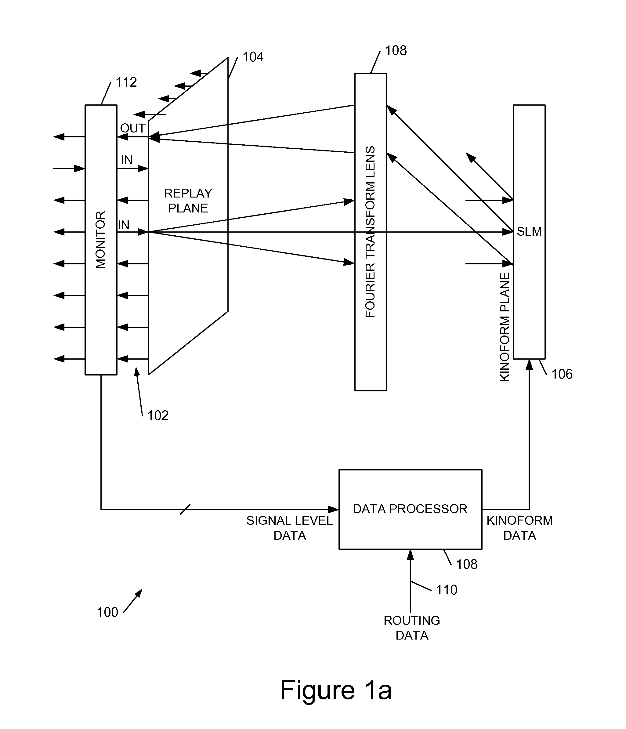
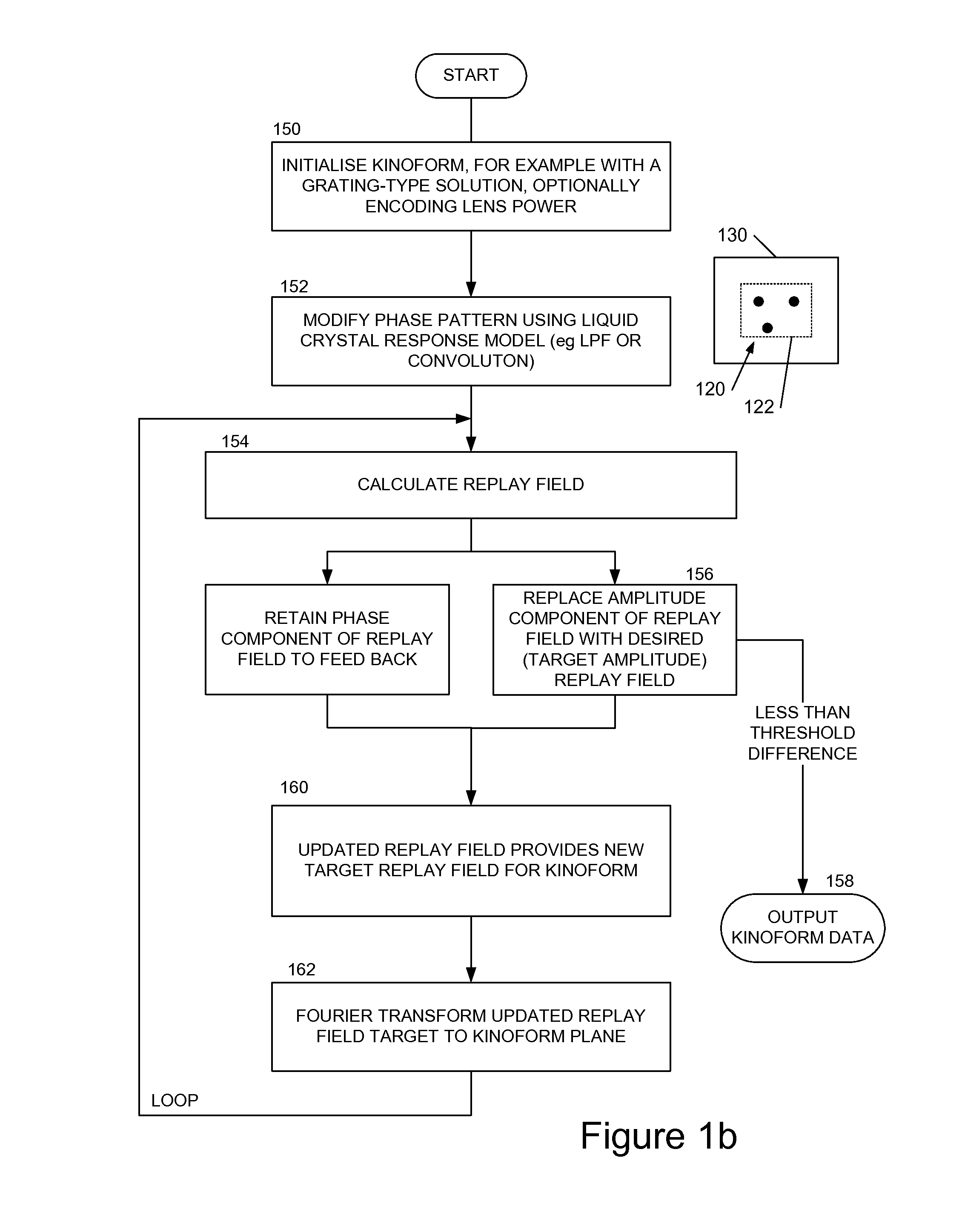
[0054]Referring to FIG. 1a, this shows an embodiment of an LCOS light beam routing device 100 according to an embodiment of the invention. A fibre optic array 102 comprises one or more input fibre optics 102a and a plurality of output fibre optics 102b, with inputs and outputs in a common plane 104 (the kinoform replay plane). An LCOS SLM 106 displays a phase pattern of a kinoform and operates in a reflective mode. A Fourier-transform lens 108 is located between the replay plane 104 and kinoform / SLM 106. The SLM is driven by a data processor 108 which has an input 110 to receive routing data for selecting an optical output. The data processor in embodiments performs the calculations as described below to determine an output kinoform data for SLM 106. In embodiments one or more of the input and / or output beams may be monitored by a beam monitor 112, for example a detector array. The skilled person will appreciate that there are many monitoring techniques which may be employed includi...


PUM


Abstract

We describe a LCOS (liquid crystal on silicon) telecommunications light beam routing device, the device comprising: an optical input; a plurality of optical outputs; a LCOS spatial light modulator (SLM) in an optical path between said input and said output, for displaying a kinoform; a data processor, coupled to said SLM, configured to provide kinoform data for displaying said kinoform on said SLM; wherein said kinoform data defines a kinoform which routes a beam from said optical input to a selected said optical output; wherein said data processor is configured to input routing data defining said selected optical output and to calculate said kinoform data for routing said beam responsive to said routing data; and wherein said data processor is configured to calculate said kinoform data by: determining an initial phase pattern for said kinoform; calculating a replay field of said phase pattern; modifying an amplitude component of said replay field to represent a target replay field for said beam routing, retaining a phase component of said replay field to provide an updated replay field; performing a space-frequency transform on said updated replay field to determine an updated phase pattern for said kinoform; and repeating said calculating and updating of said replay field and said performing of said space-frequency transform until said kinoform for display is determined; and outputting said data for display on said LCOS SLM.

Description

FIELD OF THE INVENTION[0001]This invention relates to methods and apparatus for routing light beams in telecommunications devices using holographic techniques. In particular aspects of the invention relating to displaying kinoforms on LCOS (Liquid crystal on silicon) devices.BACKGROUND TO THE INVENTION[0002]The use of holographic techniques, in particular kinoforms (phase only holograms) in telecommunications presents special problems, in particular because of the high signal-to-noise (SNR) / low crosstalk requirements as compared with display applications. For example in a display application the level of noise / crosstalk may be of order 1:300 whereas in a telecommunications device it may be of order 1:10000. other special problems which can arise are as follows:[0003]Operation at the long wavelength of 1.5 micron necessitates the use of thick liquid layers (compared with visible light devices), making the accurate rendition of the pixel array pattern in the liquid crystal more diffic...

Claims


Application Information

Patent Timeline
IPC IPC(8): G03H1/08G02B5/32G03H1/22
CPCG03H1/0841G03H1/0808G03H1/2294G02B5/32G03H2225/60G03H2001/0816G03H2210/44G03H2226/02G03H2001/085G02B6/3558G02B6/3588G02F1/136277G03H2001/0491G03H2222/31G03H2222/33G03H2223/16G03H2225/32G02B6/35G03H1/08H04Q11/0005
Inventor COLLINGS, NEILGEORGIOU, ANDREASREDMOND, MARUA MICHELLEROBERTSON, BRIANLIU, JINSONGCROSSLAND, WILLIAMMOORE, JOHN RICHARDCHU, DAPING
Owner CAMBRIDGE ENTERPRISE LTD
Why Eureka
Try Eureka