
Safety control device and safety control system

a control device and safety control technology, applied in the field of safety control devices and safety control systems, can solve problems such as reducing operating rate or increasing working area

Inactive Publication Date: 2015-10-08
FUJI ELECTRIC CO LTD
View PDF17 Cites 14 Cited by
  • Summary
  • Abstract
  • Description
  • Claims
  • Application Information

AI Technical Summary

Benefits of technology

The invention is a safety control device that uses an image detection system to monitor the position of an operator and a hazard source. The device selects a safety function based on the distance between the two, and outputs a safety signal to indicate the selected function. This ensures that the proper safety function operates based on the operator's position relative to the hazard source. Compared to existing technologies, the invention is more efficient and effective in addressing potential hazards.

Problems solved by technology

Therefore, the heretofore known technology has the problem of an increase in working area or a decrease in operating rate due to stopping the robot, power source, or the like.

Method used


Image

  • Safety control device and safety control system
  • Safety control device and safety control system
  • Safety control device and safety control system

Examples


Embodiment Construction

[0029]Hereafter, a description will be given, referring to the drawings, of an embodiment of the invention.

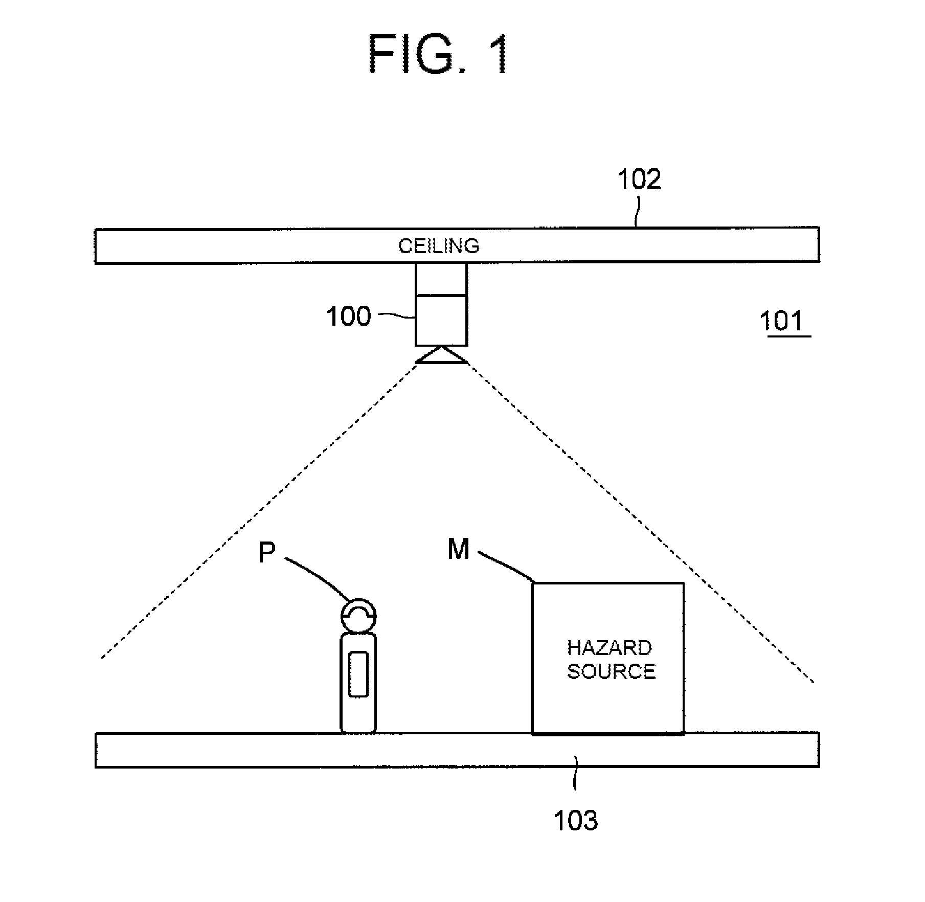
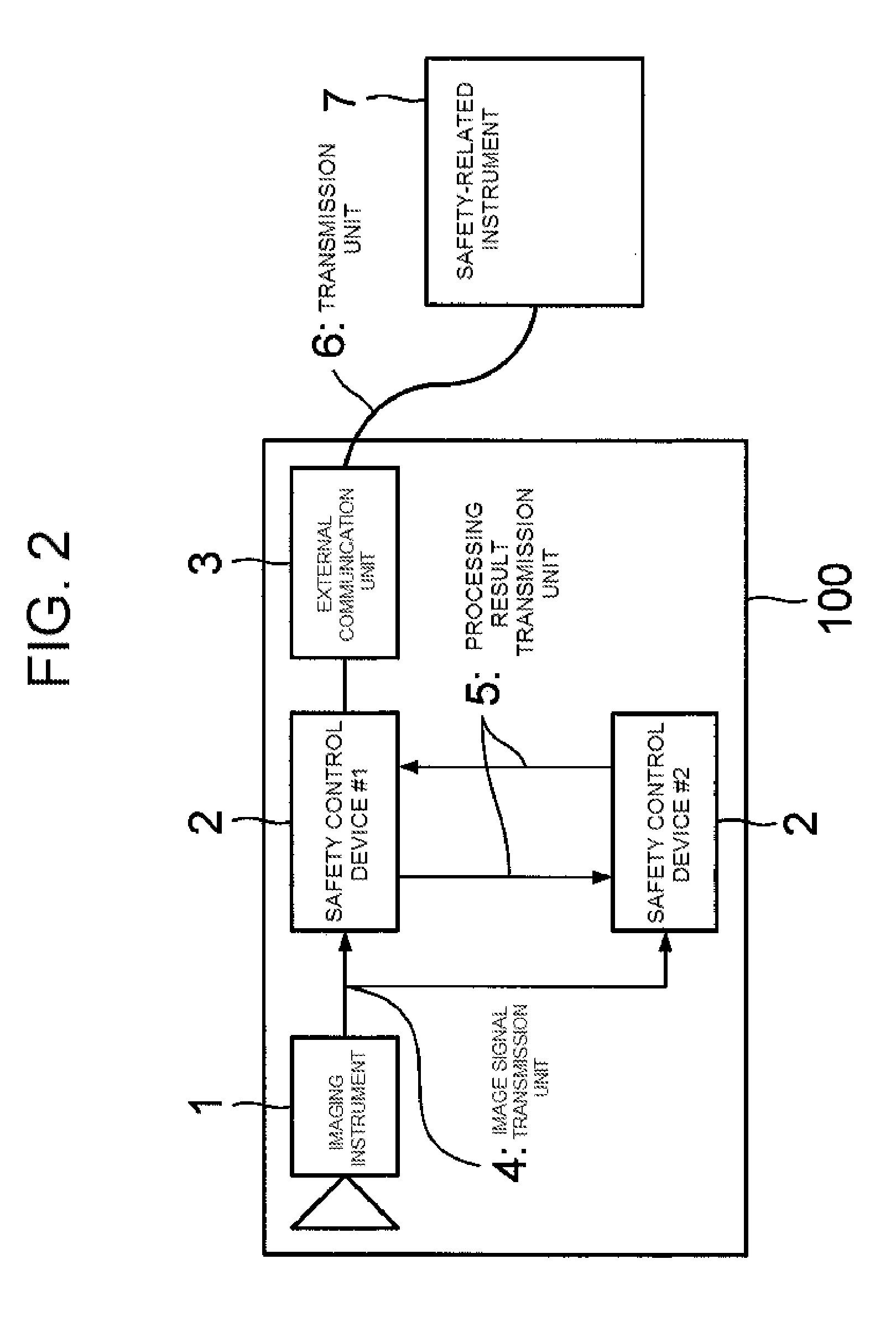
[0030]FIG. 1 is a diagram showing an example of application of a safety control system 100 according to one example of the invention. In the illustrated example, the safety control system 100 according to the embodiment is installed on a ceiling 102 of a machine room 101. In the example shown in FIG. 1, the safety control system 100, with a space on and above a floor 103 in the machine room 101 as a monitoring object area (or simply monitoring area), takes an image of the monitoring object area. If the safety control system 100 detects that a hazard source M and an operator P have come close to each other in the monitoring object area, it generates a safety signal indicating an appropriate safety function, and supplies the safety signal to a safety-related instrument. Herein, the hazard source M is a moving object, such as a multijoint robot with a wide movable range or a conve...


PUM


Abstract

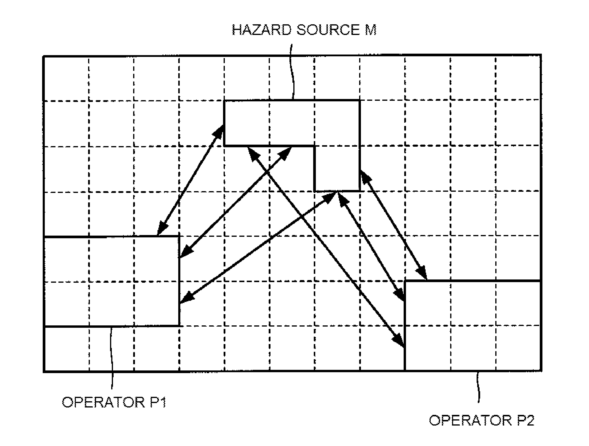
A safety control device causes an appropriate safety function to operate based on the positional relationship between an operator and a hazard source, the positions of which vary from moment to moment. A hazard source detection section and an operator detection section detect an image of the hazard source and an image of the operator, respectively, from an image of a monitoring area taken by an imaging instrument. A shortest distance search section searches for a shortest distance between the image of the hazard source and the image of the operator. A safety function allocation section selects a safety function based on the shortest distance found by the shortest distance search section. A safety signal generation section transmits a safety signal, which indicates the selected safety function, to an external safety-related instrument using an external communication unit.

Description

CROSS-REFERENCE TO RELATED APPLICATION[0001]This application claims the benefit of foreign priority of Japanese patent application 2014-077932, filed Apr. 4, 2014. The disclosure of this earlier application is incorporated herein by reference.BACKGROUND OF THE INVENTION[0002]1. Field of the Invention[0003]The present invention relates to a safety control device and a safety control system, which maintain a drive instrument, such as a servo or an inverter, in a safe condition in a control room, a machine room, or the like.[0004]2. Description of the Background Art[0005]A drive instrument using power electronics, such as a servo or an inverter, is used in a fan or pump in a factory or the like, an elevator, a machine room in a building, a drive portion of a manufacturing device, or the like. In recent years, there is a growing need for the safety of this kind of drive instrument. Therefore, JP-A-2004-282368 proposes a technology wherein an image of a hazardous region is taken in a wor...

Claims


Application Information

Patent Timeline
IPC IPC(8): G06T7/00G06T7/20H04N5/232G06V10/28
CPCG06T7/0042H04N5/23222G06T2207/30232G06T2207/10004G06T7/20F16P3/142G06T7/60G06T2207/30196G06T7/73G06V10/28H04N23/64
Inventor KOKUBUN, HIROYUKISATO, YOSHINOBU
Owner FUJI ELECTRIC CO LTD
Learn More