Resistor and manufacturing method thereof

a technology of resistors and manufacturing methods, applied in the field of resistors, can solve the problems of deterioration of resistors, damage to electronic circuits, and easy damage of carbon resistors, and achieve the effect of improving the joining strength

Active Publication Date: 2015-10-08
SMART ELECTRONICS CO LTD
View PDF6 Cites 6 Cited by
  • Summary
  • Abstract
  • Description
  • Claims
  • Application Information

AI Technical Summary

Benefits of technology

[0023]A plating layer including nickel (Ni) or titanium (Ti) may further be disposed on the surface

Problems solved by technology

In general, a resistor that is used in a circuit to restrict the flow of current causing a drop in voltage is a device consuming power to produce heat.
However, power greater than the rated power supplied to conventional resistors generally causes deterioration in the resi

Method used


Image

  • Resistor and manufacturing method thereof
  • Resistor and manufacturing method thereof
  • Resistor and manufacturing method thereof

Examples


second embodiment

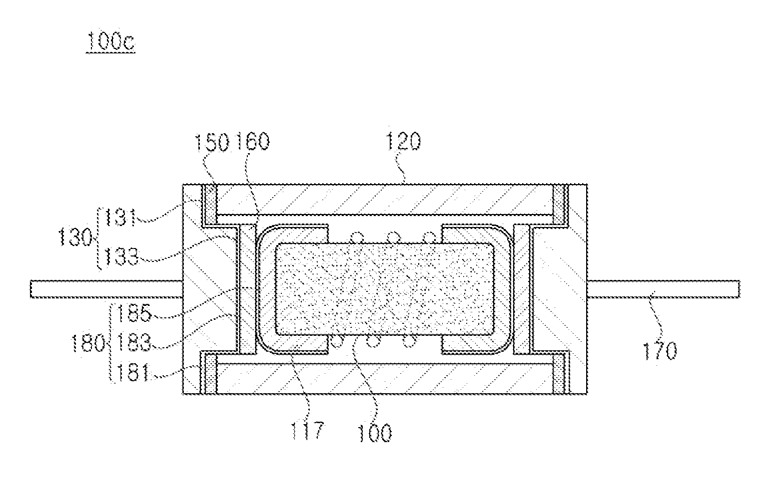
[0060]FIG. 4 is a sectional view illustrating a resistor 100a according to the present invention.

[0061]Referring to FIG. 4, the resistor 100a according to the present invention may further include brazing members 160 that join each of the contact portions 133 to each of the terminal electrodes 117.

[0062]For example, the brazing member 160 may have a plate shape and may be formed of an alloy including copper (Cu), silver (Ag), and zinc (Zn).

[0063]The brazing member 160 is melted between the contact portion 133 and the terminal electrode 117 to join the contact portion 133 to the terminal electrode 117 in the same manner as the brazing ring 150.

[0064]Thus, the resistive element 110 may be more firmly joined to the sealing electrodes 130 by use of the brazing members 160, thereby improving durability of the resistor 100a.

third embodiment

[0065]FIG. 5 is a sectional view illustrating a resistor 100b according to the present invention.

[0066]Referring to FIG. 5, each of the brazing rings 150a of the resistor 100b according to the present invention may be configured to be joined to both of the ceramic tube 120 and the resistive element 110.

[0067]That is, the brazing ring 150a may include an outer portion 153 that is joined to an end of the ceramic tube 120 and an inner portion 154 that is joined to an end portion of the resistive element 110, particularly, the terminal electrode 117.

[0068]Thus, the brazing ring 150a may have a thickness identical to or greater than that of the contact portion 133a. This is because, when the thickness of the brazing ring 150a is greater than that of the contact portion 133a, the brazing ring 150a may be joined to both the ceramic tube 120 and the terminal electrode 117 after being melted.

[0069]In addition, the inner portion 154 of the brazing ring 150a may be formed to extend inward to a...


PUM

PropertyMeasurementUnit
Temperatureaaaaaaaaaa
Strengthaaaaaaaaaa

Abstract

A resistor and a manufacturing method thereof are disclosed. Since a ceramic tube formed of a ceramic material is used and the ceramic tube is joined to sealing electrodes by use of brazing rings, joining strength and durability of the resistor are considerably improved. The resistor may be stably used at a high voltage due to excellent heat dissipation characteristics thereof.

Description

BACKGROUND OF THE INVENTION[0001]1. Field of the Invention[0002]The present invention relates to a resistor and a manufacturing method thereof, and more particularly to a resistor having improved joining strength and durability, since a ceramic tube formed of a ceramic material is used and the ceramic tube is joined to sealing electrodes by use of brazing rings, and stably used at a high voltage due to excellent heat dissipation characteristics, and a manufacturing method thereof.[0003]2. Description of the Related Art[0004]In general, a resistor that is used in a circuit to restrict the flow of current causing a drop in voltage is a device consuming power to produce heat. A maximum power consumed thereby is set as the rated power. Resistors commonly used in electronic circuits have a power rating of about ⅛ to about ½ W, and resistors with a high power rating are used in power supplies.[0005]FIG. 10 is a sectional view illustrating a conventional resistor. The conventional resistor...

Claims


Application Information

Patent Timeline
IPC IPC(8): H01C1/024H01C17/02B23K35/30B23K1/00B23K1/19B23K35/02H01C1/026H01C17/28
CPCH01C1/024H01C1/026H01C17/02B23K35/3006B23K1/0016B23K1/19B23K35/0222H01C17/28H01C1/014H01C1/08H01C1/144H01H85/048H01C7/00
Inventor JUNG, JONG ILKANG, DOO WONAHN, GYU JINJIN, SANG JOONKIM, HYUN CHANGLEE, KYUNG MI
Owner SMART ELECTRONICS CO LTD
Why Eureka
Try Eureka