Energy harvester

a technology of energy harvester and energy storage, which is applied in the direction of relays, generators/motors, relays, etc., can solve the problems of lowering efficiency, leakage current in transistors and thyristors, and consuming electricity of transistors and thyristors, so as to improve the efficiency of energy harvester and simplify control devices. , the effect of increasing the efficiency of the energy harvester

Active Publication Date: 2015-10-08
COMMISSARIAT A LENERGIE ATOMIQUE ET AUX ENERGIES ALTERNATIVES +2
View PDF1 Cites 4 Cited by
  • Summary
  • Abstract
  • Description
  • Claims
  • Application Information

AI Technical Summary

Benefits of technology

[0024]the use of an electrostatic or piezoelectric transducer or of a spark gap to produce the control device limits its consumption and therefore makes it possible to increase the efficiency of the energy harvester and also makes it possible simply to mechanically set the predetermined threshold beyond which the switch must be closed;
[0025]using a spark gap as switch simplifies the control device since the latter is then incorporated within the very switch;
[0026]using a converter comprising a first electromechanical transducer and a second transducer suitable for exerting a stress on this first transducer makes it possible to generate electricity even from very slow variations of the energy to be harvested and to limit the bulk of the converter;
[0027]using a thermomechanical transducer as second transducer of the converter makes it possible to harvest electrical energy from a temperature variation and avoid having recourse to radiators to impose a temperature gradient;
[0028]using a material with shape memory makes it possible to exert greater stresses on the electromechanical transducer;
[0029]using a piezoelectric material as first transducer of the converter makes it possible to simply transform a stress variation into electricity.

Problems solved by technology

The applicant has discovered that when the quantity of energy that can be harvested is small and the time taken to harvest it is long, the lowering of the efficiency was partly due to the use of solid state switches in the collection circuit.
In effect, the transistors and thyristors or similar consume electricity when they switch between their closed and open positions.
Furthermore, even in the open position, there is always a leakage current in the transistors and thyristors.
This problem of discharging of the first converter by leakage currents is all the greater when the variations of the energy to be harvested are slow and therefore the switching frequency of the switches is low.
Thus, the presence of transistors or thyristors in the known energy harvesters reduces their efficiency.

Method used


Image

  • Energy harvester
  • Energy harvester
  • Energy harvester

Examples


Embodiment Construction

[0037]In the figures, the same references are used to denote the same elements.

[0038]Hereinafter in this description, the features and functions that are well known to those skilled in the art are not described in detail.

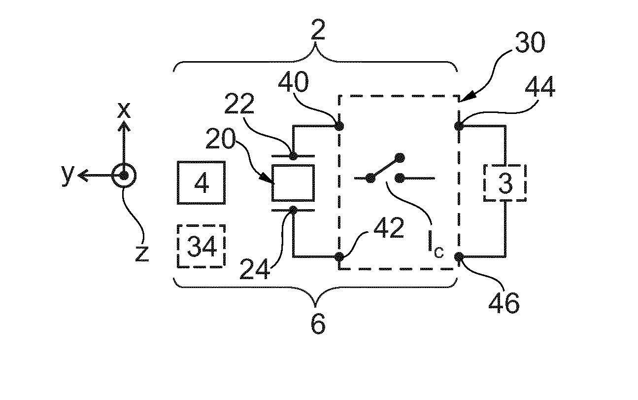
[0039]FIG. 1 represents an electricity generator 2 for powering an electrical load. In this particular case, the electrical load is a load capable of storing electrical energy. For example, it is a capacitor 3.

[0040]The generator 2 comprises a source 4 of energy to be harvested and a harvester 6 of this energy. The harvester 6 powers the capacitor 3 from the energy harvested.

[0041]The source 4 is a source of energy freely available in the environment of the harvester 6.

[0042]The harvester 6 comprises a converter 20, a collection circuit 30 and a control device 34 for the circuit 30.

[0043]The converter 20 converts a variation of the energy to be harvested into a corresponding excess of electrical charges on one connection terminal 22 or 24 relative to the other conne...


PUM


Abstract

An energy harvester having a converter suitable for converting a variation of the energy to be harvested into a corresponding excess of electrical charges. There is a circuit for collecting the excess of electrical charges, the circuit is equipped with a controllable switch and a control device for the switch designed to control the switching of this switch to its closed position. The control device is suitable for exerting a force which stresses the electrical contacts towards one another. The force varies continually as a function of the quantity of electrical charges present on the first terminal and bringing the electrical contacts to bear on one another only when the excess of electrical charges exceeds a predetermined threshold, and/or for ionizing the electrically insulating medium to produce an electrical arc between the two electrical contacts only when the excess of electrical charges exceeds the predetermined threshold.

Description

RELATED APPLICATIONS[0001]This application is a U.S. National Stage of international application number PCT / EP2013 / 071509 filed Oct. 15, 2013, which claims the benefit of the priority date of French Patent Application FR 1260047, filed Oct. 22, 2012, the contents of which are herein incorporated by reference.FIELD OF INVENTION[0002]The invention relates to an energy harvester for the implementation of an electricity generator.BACKGROUND[0003]Self-powered systems such as, for example, arrays of wireless standalone sensors require an in-situ electricity generator. These systems are often complex and comprise numerous elements which are often installed out of reach. In these situations, maintenance of the system is complicated and costly if, for example, a discharged battery replacement were to become necessary. It is therefore desirable not to replace the battery throughout the lifetime of the system in order to reduce the maintenance costs and eliminate the associated waste products....

Claims


Application Information

Patent Timeline
Patent Type & Authority Applications(United States)
IPC IPC(8): H01H59/00
CPCY10T307/826H01H59/00H02N2/18H02N2/181H10N30/00H10N30/304H10N30/306H02N2/186H02N10/00
Inventor DELAMARE, JEROMEVIALA, BERNARDCUGAT, ORPHEERICART, THIBAULT
Owner COMMISSARIAT A LENERGIE ATOMIQUE ET AUX ENERGIES ALTERNATIVES
Why Eureka
Try Eureka