System and Method for Detection of Motor Vibration

a technology of vibration detection and detection system, which is applied in the direction of motor/generator/converter stopper, dynamo-electric converter control, dynamo-electric gear control, etc., can solve the problems of increasing wear on the motor, reducing the throughput of the controlled machine, and generating vibration or resonance within the control system. , to achieve the effect of reducing the detected vibration in the motor, reducing or eliminating the identified vibration, and reducing or eliminating the isolated vibration

Active Publication Date: 2015-10-08
ROCKWELL AUTOMATION TECH
View PDF4 Cites 150 Cited by
  • Summary
  • Abstract
  • Description
  • Claims
  • Application Information

AI Technical Summary

Benefits of technology

[0006]The subject matter disclosed herein describes an improved system for monitoring vibration of an electric machine and for adjusting operation of the motor to reduce vibration detected in the motor. Sensors are positioned within the motor housing to detect vibrations of the electric machine. According to one embodiment, each sensor is positioned in a plane orthogonal to the motor shaft. A first sensor is mounted on one side of the motor shall and a second sensor is mounted on the opposite side of the motor shaft. Each sensor detects vibration along at least one axis of the motor and the sensors are oriented such that the polarity of each sensor is reversed. In other words, a signal from a first sensor corresponding to vibration in one direction along one of the axes has a positive magnitude while a signal fro

Problems solved by technology

Due to the rotational nature of an electric machine, imbalances, for example, on the rotor shaft; misalignments, for example, between the motor shaft and the gearbox; complaint mechanical loads, such as couplings between a motor shaft and a gearbox; or even torque ripple due to machine construction, can result in vibrations or resonance being generated within the control system.
Such vibrations or resonances may result in increased wear on the motor or re

Method used


Image

  • System and Method for Detection of Motor Vibration
  • System and Method for Detection of Motor Vibration
  • System and Method for Detection of Motor Vibration

Examples


Embodiment Construction

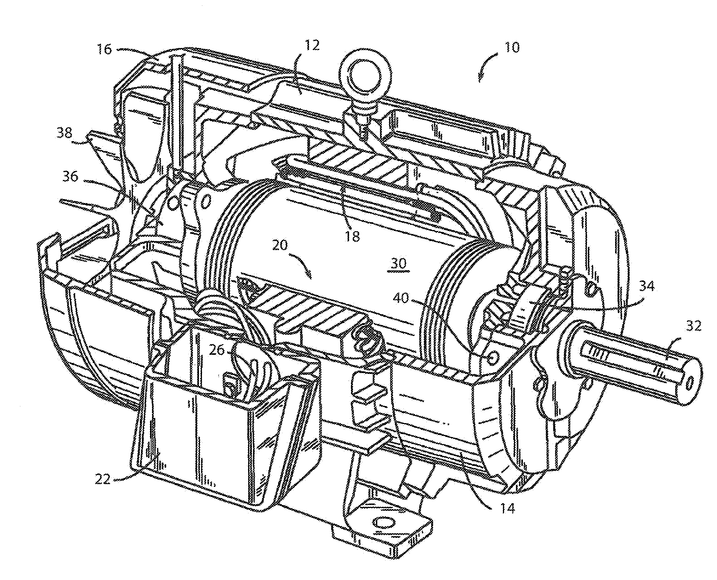
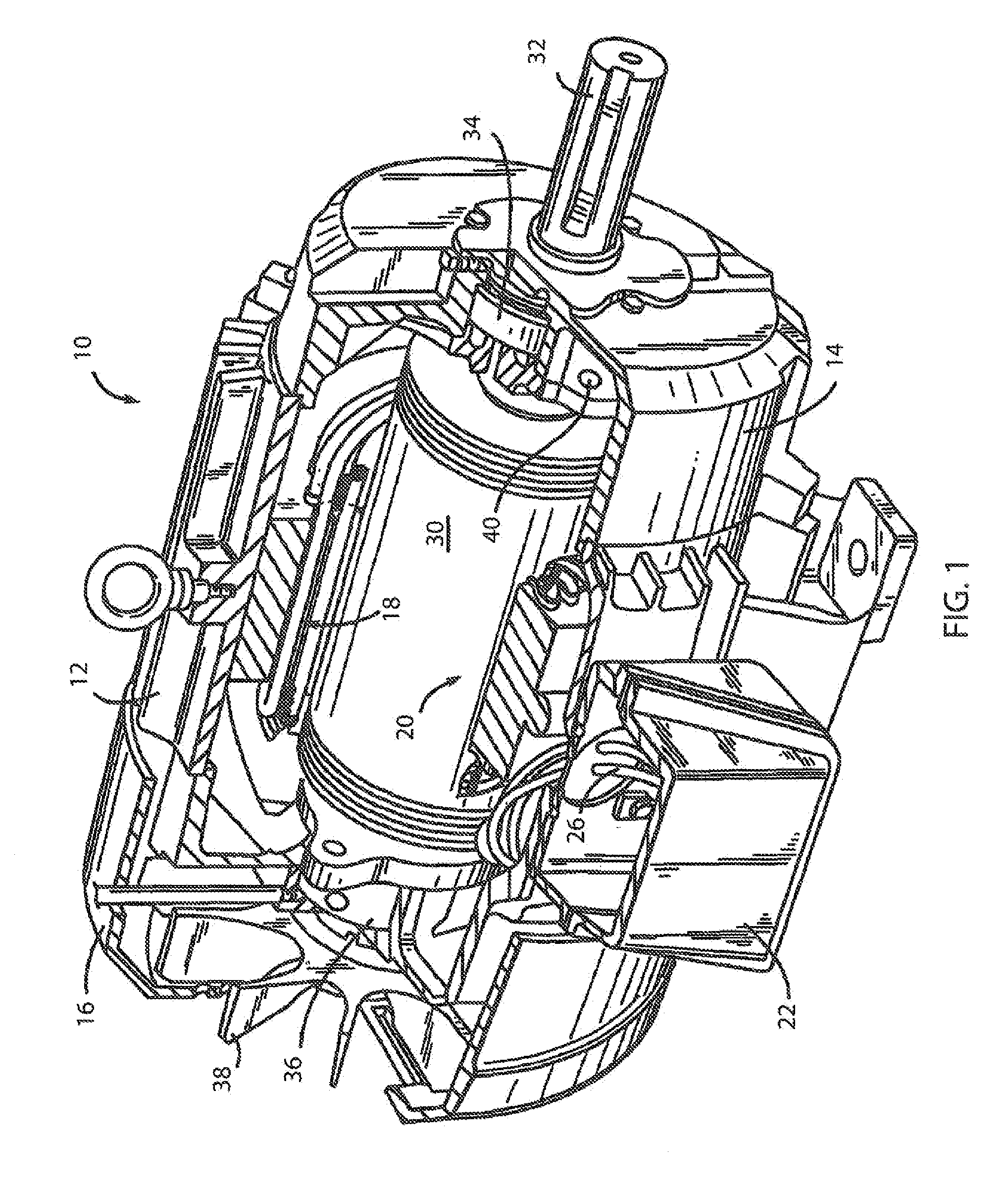
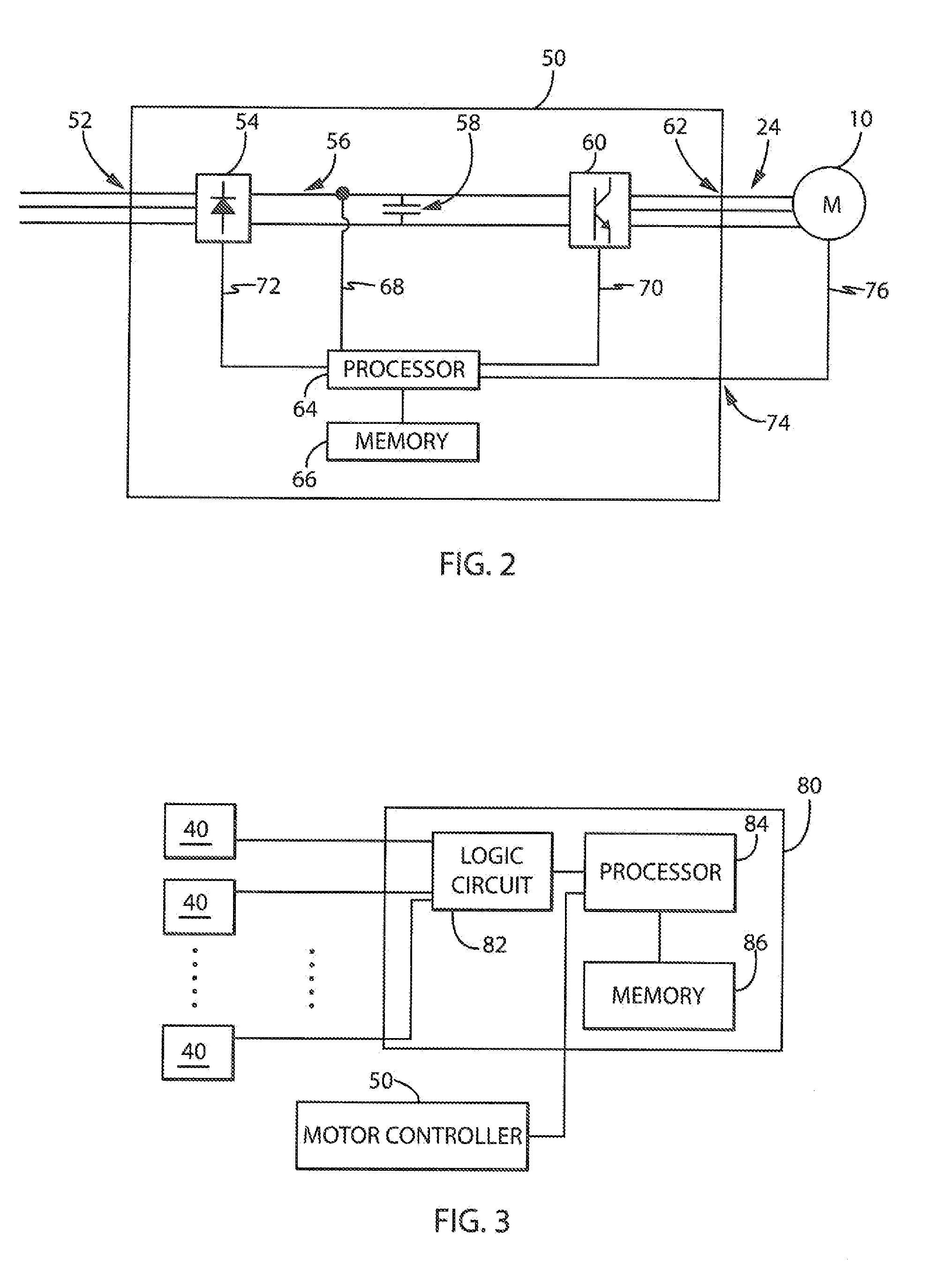
[0018]Turning initially to FIG. 1, an exemplary motor 10 incorporating a system to mitigate vibration of the motor 10 according to one embodiment of the invention is illustrated. The motor 10 includes a frame 12 open at each end. A front end cap 14 and a rear end cap 16 enclose each end and, in combination with the frame 12, define a housing for the motor 10. The motor 10 includes a stator assembly 18, configured to receive a voltage to control operation of the motor 10, and a rotor assembly 20 configured to rotate as a function of the voltage applied to the stator assembly 18. A junction box 22 is mounted to the frame 12 and is configured to receive motor leads 24 from a motor controller 50 (as shown in FIG. 2) which are, in turn, connected to leads 26 from the stator assembly 18 within the junction box 22, establishing an electrical connection between the stator assembly 18 and the motor controller 50.

[0019]The rotor assembly 20 includes a rotor 30 and a motor shaft 32. The motor ...


PUM


Abstract

An improved system for monitoring vibration of an electric machine is disclosed. According to one embodiment, sensors are positioned in a plane orthogonal to the motor shaft and each sensor detects vibration along at least one axis of the motor. The sensors are oriented such that the polarity of each sensor is reversed. The pairs of sensors may be used to isolate specific vibrations within the motor. According to another embodiment, a sensor may be mounted directly to the motor shaft. The sensor on the motor shaft directly detects vibrations along the motor shaft. Optionally, a second sensor may be mounted to a fixed location within the motor housing, and the combination of the sensor on the motor shaft and the sensor at a fixed location may be used to isolate specific vibrations within the motor. A motor controller may adjust operation of the motor to reduce the isolated vibration.

Description

BACKGROUND OF THE INVENTION[0001]The subject matter disclosed herein relates generally to control of an electric motor and, more specifically, to a system for detecting vibrations using sensors mounted to the electric motor and reducing the detected vibrations using a controller connected to the electric motor.[0002]Electrical rotating machines, such as electric motors or generators, have become widespread and are found in numerous applications and configurations. Electric machines include a stationary component (i.e., the stator) and a rotating component (i.e., the rotor). In electric motors, a magnetic field is established in the rotor, for example via magnets mounted to the rotor or via an electrical current applied to or induced in a coil wound on the rotor. A second, rotating magnetic field is established as a result of the application of a controlled voltage to the stator, and the rotation of the magnetic field in the stator causes the magnetic field in the rotor to rotate, th...

Claims


Application Information

Patent Timeline
IPC IPC(8): H02K11/00H02P21/14G01M1/14
CPCH02K11/001H02P21/14G01M1/14H02K5/24H02K11/20
Inventor COOPER, MARKBRONK, KELLY J.QIAN, WEIYUAN, ZHENHUANRAMANARAYANAN, SHANKERNARAYANSAWANT, MANASFENG, SHUNSCHMIDT, ROBERT H.
Owner ROCKWELL AUTOMATION TECH
Why Eureka
Try Eureka