Separator for separating fluid and scr urea injection system using the same

a separation device and urea injection technology, applied in the direction of liquid degasification, separation processes, instruments, etc., can solve the problems of customer complaints, severe limit the emission standards of nitrogen oxides, and the gradual strictness of emission gas regulations of vehicles using fossil fuels. , to achieve the effect of ensuring the performance of injection, preventing customer complaints, and high speed

Inactive Publication Date: 2015-10-15
HYUNDAI MOTOR CO LTD
View PDF13 Cites 7 Cited by
  • Summary
  • Abstract
  • Description
  • Claims
  • Application Information

AI Technical Summary

Benefits of technology

[0032]According to the present invention, it is possible to prevent customer complaints due to ammonia gas that is generated when the urea is injected, ensure performance in injecting the urea when the urea is injected at a high speed using an injection gun, and ensure pressure safety in the system after the urea is injected.

Problems solved by technology

As problems regarding environmental pollution have become a major social issue, emission gas regulations on vehicles having internal combustion engines that use fossil fuel are gradually getting strict.
Particularly, because a nitrogen oxide (NOx), which is known as a substance that causes acid rain and respiratory diseases, is included in exhaust gas from a vehicle having a diesel engine, which uses diesel fuel, such as a bus or a truck, regulations on gas emission standard for a vehicle, which has been applied recently or will be applied, more severely limit emission standards of nitrogen oxides.
Accordingly, customer complaints may occur due to deterioration in injection performance because of injecting urea at a high speed, and an unpleasant odor due to ammonia gas that is generated when the urea is injected.

Method used


Image

  • Separator for separating fluid and scr urea injection system using the same
  • Separator for separating fluid and scr urea injection system using the same
  • Separator for separating fluid and scr urea injection system using the same

Examples


Embodiment Construction

[0047]Reference will now be made in detail to various embodiments of the present invention(s), examples of which are illustrated in the accompanying drawings and described below. While the invention(s) will be described in conjunction with exemplary embodiments, it will be understood that the present description is not intended to limit the invention(s) to those exemplary embodiments. On the contrary, the invention(s) is / are intended to cover not only the exemplary embodiments, but also various alternatives, modifications, equivalents and other embodiments, which may be included within the spirit and scope of the invention as defined by the appended claims.

[0048]Hereinafter, the present invention will be described so that those skilled in the technical field to which the present invention pertains may carry out the present invention.

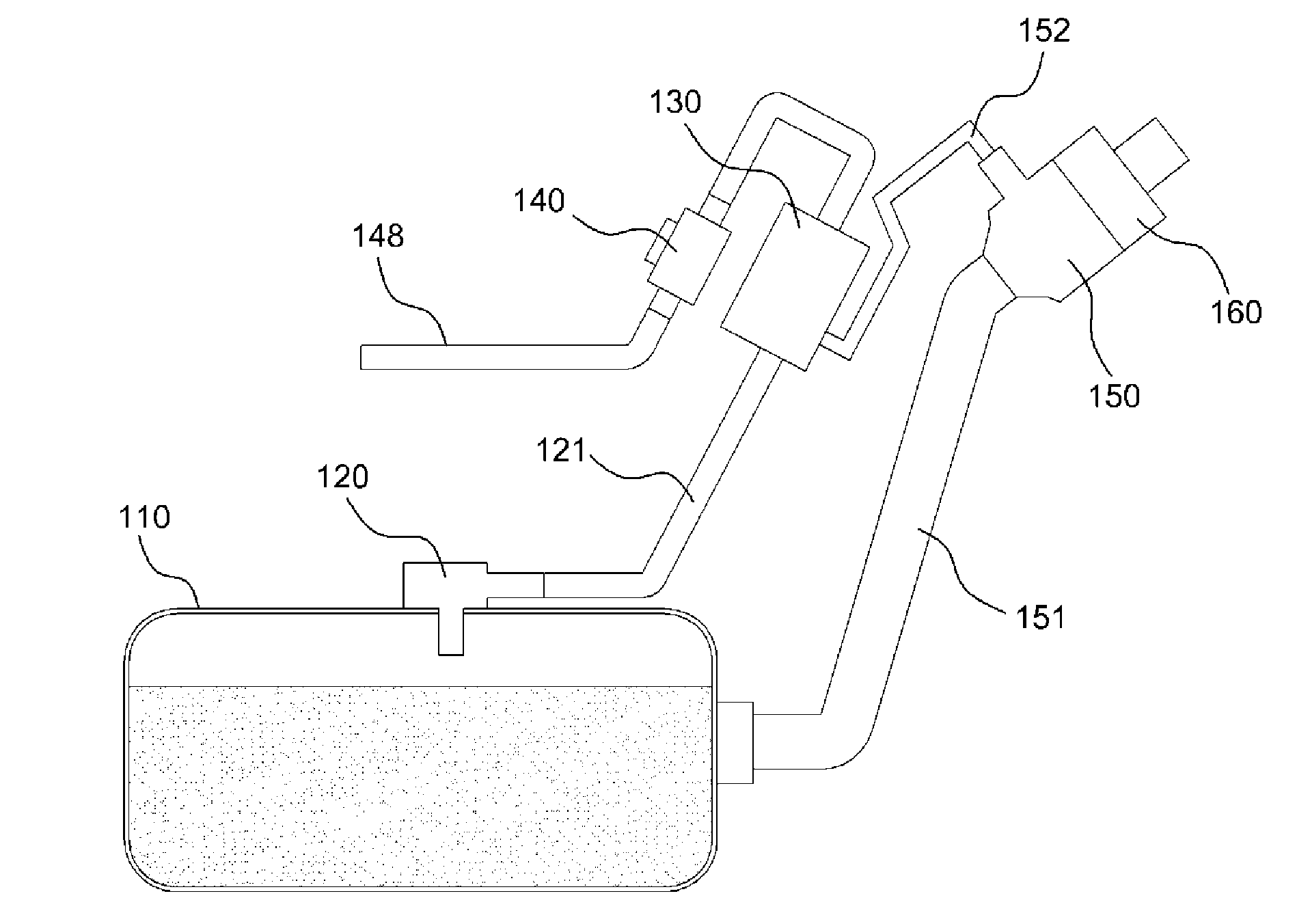
[0049]As illustrated in FIG. 1, an SCR urea injection system according to an exemplary embodiment of the present invention includes a urea tank 110, a l...


PUM

PropertyMeasurementUnit
liquid resistanceaaaaaaaaaa
pressureaaaaaaaaaa
frequencyaaaaaaaaaa

Abstract

A separator apparatus for separating fluid may include a fluid inlet port into which the fluid in which gas and liquid may be mixed flows while being pressurized, a lower body which has a partition wall formed in an internal space of the lower body that fluid-communicates with the fluid inlet port, and an upper body which may be assembled to an upper opening portion of the lower body, and has a first gas discharge port that fluid-communicates with the internal space of the lower body to discharge gaseous fluid flowing into the lower body, wherein the partition wall divides the internal space of the lower body into a central portion and an outer peripheral portion on a basis of an axis thereof.

Description

CROSS-REFERENCE TO RELATED APPLICATION[0001]The present application claims priority to Korean Patent Application No. 10-2014-0043369 filed on Apr. 11, 2014, the entire contents of which is incorporated herein for all purposes by this reference.BACKGROUND OF THE INVENTION[0002]1. Field of the Invention[0003]The present disclosure relates to a separator for separating fluid and a Selective Catalytic Reduction (SCR) urea injection system using the same. More particularly, it relates to a separator which may separate gas from a fluid in which liquid and gas are mixed, and may discharge the gas, and an SCR urea injection system which may separate and discharge urea gas, which is generated when urea is injected, using the separator.[0004]2. Description of Related Art[0005]As problems regarding environmental pollution have become a major social issue, emission gas regulations on vehicles having internal combustion engines that use fossil fuel are gradually getting strict. Particularly, bec...

Claims


Application Information

Patent Timeline
Patent Type & Authority Applications(United States)
IPC IPC(8): B01D53/94B01D19/00
CPCB01D19/0073B01D53/9431F01N3/2066F01N2610/02F01N2610/1406F01N2610/1466B01D45/16B01D45/12B01D45/08A47L9/1683B01D50/20F01N3/208
Inventor HAM, CHANG HORYOO, DONG MYOUNG
Owner HYUNDAI MOTOR CO LTD
Why Eureka
Try Eureka