

System and Method for Detecting Biofilm Growth in Water Systems
a biofilm and water system technology, applied in the field of biofilm growth detection systems, can solve the problems of increasing operating costs and maintenance costs of fluid systems, unnecessary damage to components of fluid systems, and anthropogenic water or fluid systems such as cooling towers and boilers, so as to save the amount of dye used, easy installation and replacement, and easy connection of components
- Summary
- Abstract
- Description
- Claims
- Application Information
AI Technical Summary
Benefits of technology
Problems solved by technology
Method used
Image

Examples
Embodiment Construction
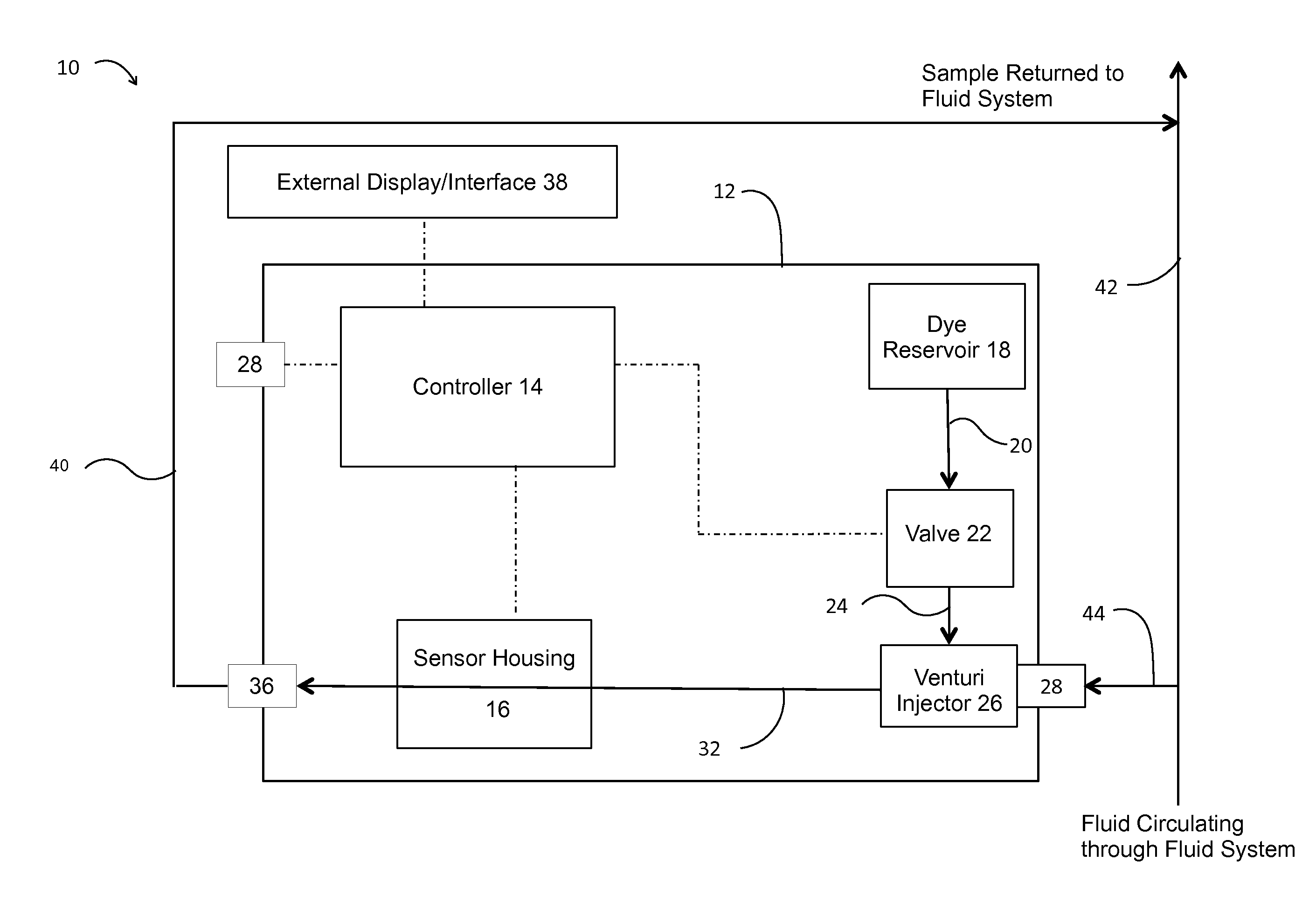
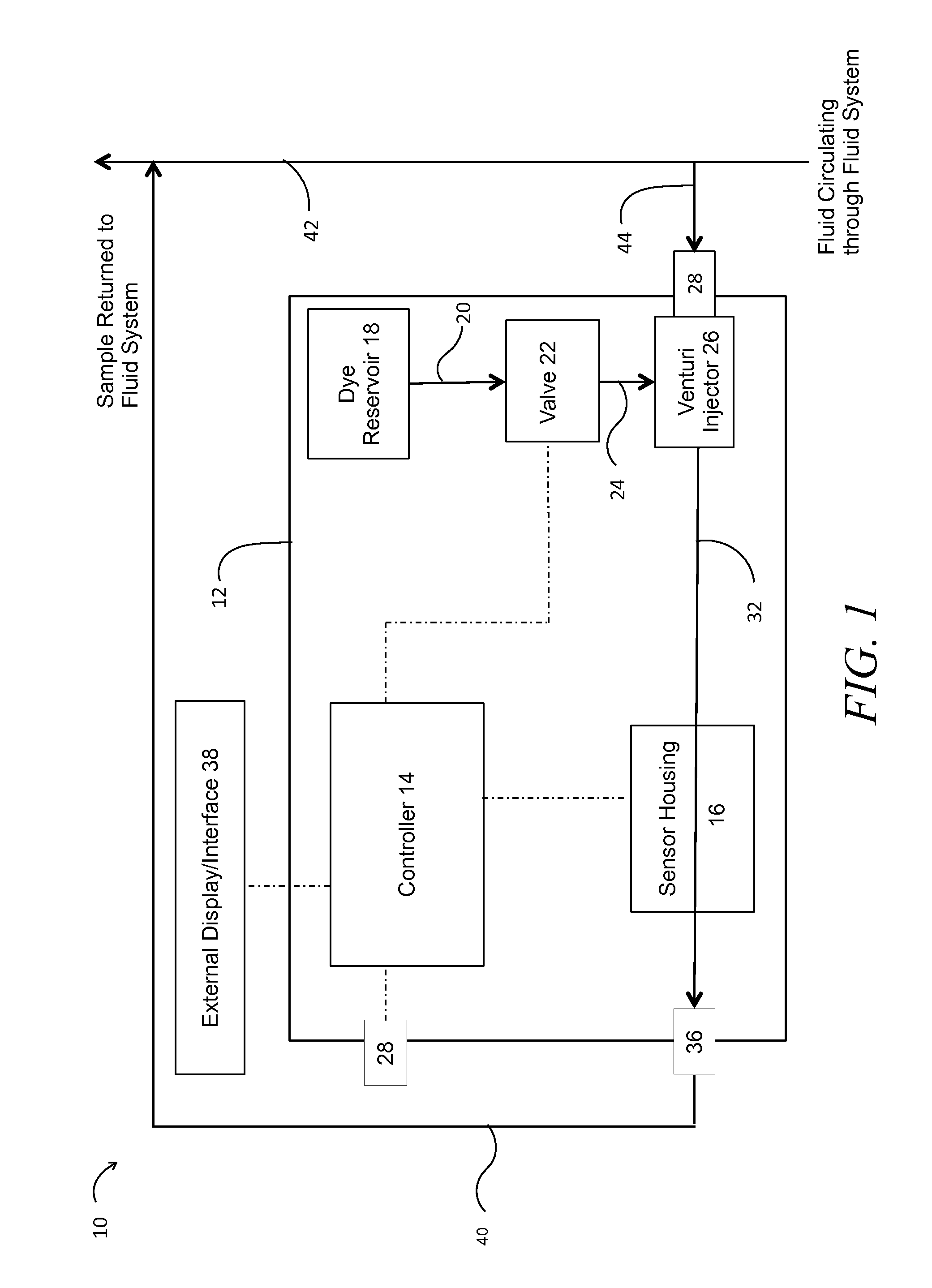
[0026]Referring to FIG. 1, a preferred embodiment of a biofilm detecting or monitoring system 10 is depicted in simple, block diagram form. Biofilm detecting or monitoring system 10 preferably comprises a housing 12, a controller 14, a sensor housing 16, a dye reservoir 18, a valve 22, a venturi 26, an inlet port 28, an outlet port 34, and optionally a USB or other type of port 28 for transmission of data received by the controller 14 from a sensor within sensor housing 16. Monitoring system 10 also preferably comprises a plurality of tubing or conduit segments, such as 20, 24, 30, and 32 connecting various components as further described below.
[0027]Housing 12 is preferably a waterproof or water-resistant box having a removable or openable cover or door allowing access to the interior of housing 12, such as for maintenance or replenishment of the dye in dye reservoir 18. The controller 14, sensor housing 16, dye reservoir 18, valve 22, and venturi 26 are all preferably disposed wit...
PUM
| Property | Measurement | Unit |
|---|---|---|
| volume ratio | aaaaa | aaaaa |
| sizes | aaaaa | aaaaa |
| wavelength range | aaaaa | aaaaa |
Abstract
Description
Claims
Application Information