Miniature lens assembly and method of making same

a technology of miniature lenses and lens assemblies, applied in the field of miniature lens assemblies, can solve the problems of lens assembly rejection, reduced image quality, and continued demand for smaller and higher quality low cost imaging lens assemblies,

Active Publication Date: 2015-10-15
MEMS START
View PDF2 Cites 31 Cited by
  • Summary
  • Abstract
  • Description
  • Claims
  • Application Information

AI Technical Summary

Benefits of technology

[0018]In an alternative embodiment, the movable lens has a smooth interface with respect to the adjacent lens so that the movable lens can slide on the surface of the adjacent lens without a substantial change in tip, tilt or spacing between the lenses.
[0019]In another embodiment, the movable lens has a smooth surface on its outer diameter so that the movable lens can slide along the lens barrel optical axis without a substantial change in tip, tilt, or decenter. In yet another embodiment, the movable lens is inside of a first portion of the lens barrel and the remaining lenses are inside of a second portion of the lens barrel and the two portions of the lens barrel are aligned and then fixed to each other in the aligned position.

Problems solved by technology

The continuing demand for smaller and higher quality low cost imaging lens assemblies presents a considerable challenge to optical and mechanical design.
Alignment errors between the lenses lead to a reduction in image quality.
When the image quality of a lens assembly is not acceptable, the lens assembly is rejected.
This leads to undesirable yield loss in the manufacturing of lens assemblies.
The increase in the number of optical elements that are stacked up tends to increase the impact of any alignment errors.
As a result, the yield loss in the manufacture of lens assemblies using prior art passive alignment becomes worse when the number of lenses in the assembly increases.
The larger aperture designs magnify the sensitivity to lens alignment errors and the yield loss in the manufacture of lens assemblies using prior art passive alignment becomes worse.
However, known active alignment techniques, such as using an autocollimator and a rotational stage to individually align lenses can be too complex and costly for high-volume production of miniature lens assemblies.

Method used


Image

  • Miniature lens assembly and method of making same
  • Miniature lens assembly and method of making same
  • Miniature lens assembly and method of making same

Examples


Embodiment Construction

[0034]In accordance with embodiments further described herein, various lens assemblies are provided which may be used in miniature cameras or miniature projectors included in, for example, portable electronic devices such as cellphones.

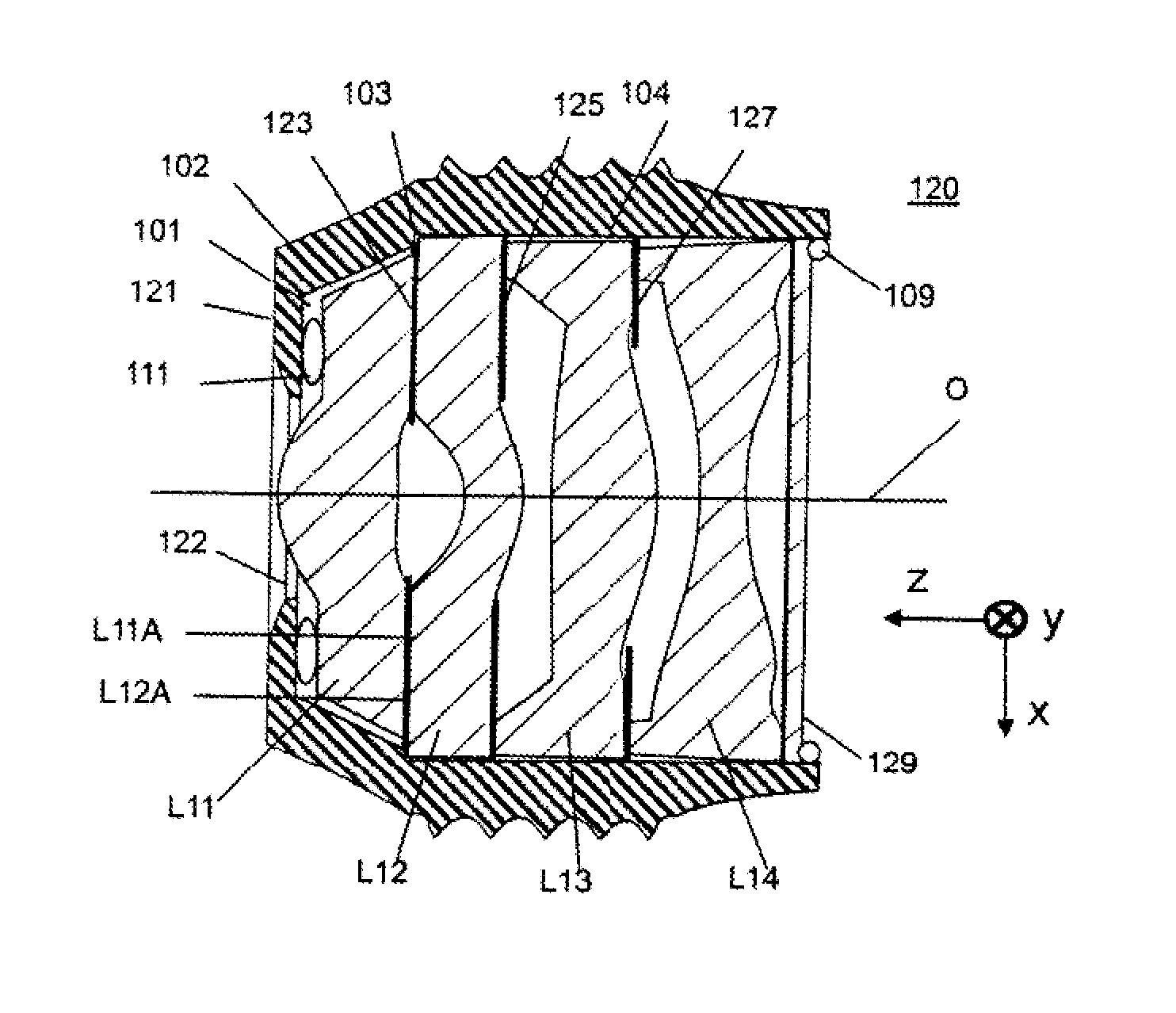
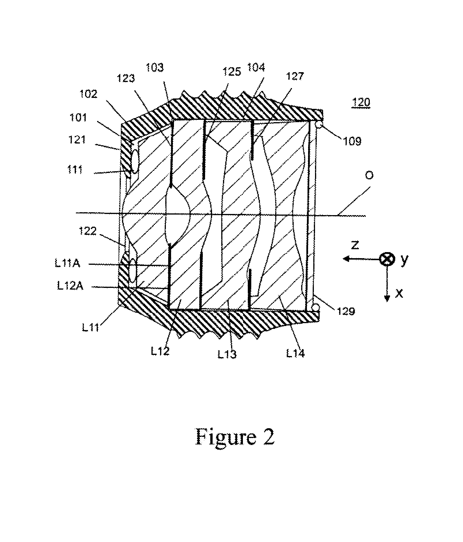
[0035]Referring now to the drawings, which are included for the purposes of illustrating embodiments of the invention, and not for limiting the same, FIG. 2 shows a cross-sectional view of a lens assembly in accordance with one embodiment of the present invention. The lens assembly 120 is comprised of four lenses L11, L12, L13 and L14, three baffles 123, 125, and 127 and an IRCF (infra-red cut filter) 129 inserted in a lens barrel 121. The baffles are interspersed between the lenses as shown. Lenses L11, L12, L13 and L14 are made of conventional lens material such as glass, plastic, optical crystal or the like. Baffles 123, 125, and 127 are made of conventional baffle material such as plastic, cloth, paper, or the like. Lens barrel 121 is made of conv...


PUM

PropertyMeasurementUnit
diameteraaaaaaaaaa
degree of freedomaaaaaaaaaa
opticalaaaaaaaaaa

Abstract

A lens assembly includes at least a pair of lenses fixed in a lens barrel and an additional lens initially having at least one degree of freedom of movement with respect to the other lenses. The additional lens can be fixed in a desired alignment position with respect to the other lenses.

Description

CROSS-REFERENCE TO RELATED APPLICATIONS[0001]This application claims priority to U.S. Provisional Patent Application Ser. No. 61 / 977,906, filed Apr. 10, 2014, the entirety of which is incorporated herein by reference.TECHNICAL FIELD[0002]This disclosure relates to lens assemblies in general, and in particular, to miniature lens assemblies for use in miniature cameras and projectors.BACKGROUND[0003]Various portable electronic devices such as cell phones and laptops use digital cameras to capture photographs and video and are expected to use digital projectors to display photographs or video on a screen or on an object. These are miniature digital cameras and include a miniature lens assembly, i.e., a lens assembly having a lens diameter of about 0.25 inches or less, which captures the light and focuses it onto a CMOS imager to capture an image. Inside a miniature projector, a lens assembly focuses the light from an LED array onto a screen or an object. The continuing demand for small...

Claims


Application Information

Patent Timeline
Patent Type & Authority Applications(United States)
IPC IPC(8): G02B13/00B32B37/14B32B37/12G02B7/02B32B37/18
CPCG02B13/0015G02B7/021B32B37/18B32B2551/00B32B37/142B32B2307/412B32B37/1292G02B7/023G03B43/00G02B7/025G02B13/001G02B13/0035G02B13/004G02B13/0045
Inventor GUTIERREZ, ROMAN CARLOS
Owner MEMS START
Why Eureka
Try Eureka