Magnetic field detector based on perpendicular exchange coupling and preparing and use methods thereof

A vertical exchange coupling and detector technology, applied in the direction of the magnitude/direction of the magnetic field, devices using electro-magnetic effects, and the manufacture/processing of electromagnetic devices, which can solve the problem of weakening output signals, increasing noise, and signal instability, etc. problem, to achieve the effect of flat adhesion, low cost and simple preparation method

Active Publication Date: 2014-07-02
TSINGHUA UNIV
View PDF4 Cites 7 Cited by
  • Summary
  • Abstract
  • Description
  • Claims
  • Application Information

AI Technical Summary

Problems solved by technology

PHE sensors are usually made of in-plane magnetized materials, which are easy to obtain a linear response. However, the reduction in the size of PHE sensors will make the magnetization state of the sensitive layer affected by thermal effects and external magnetic fields, resulting in increased noise and signal instability. and attenuation of the output signal

Method used


Image

  • Magnetic field detector based on perpendicular exchange coupling and preparing and use methods thereof
  • Magnetic field detector based on perpendicular exchange coupling and preparing and use methods thereof
  • Magnetic field detector based on perpendicular exchange coupling and preparing and use methods thereof

Examples


preparation example Construction

[0024] The present invention is based on the preparation method of the magnetic field detector of vertical exchange coupling, specifically comprises the following steps:

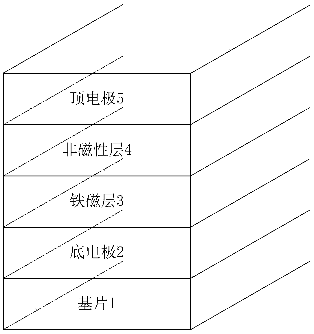
[0025] 1) The bottom electrode 2, the ferromagnetic layer 3, the non-magnetic layer 4 and the top electrode 5 are sequentially deposited on the substrate 1 by magnetron sputtering or electron beam evaporation to obtain a multilayer film structure.

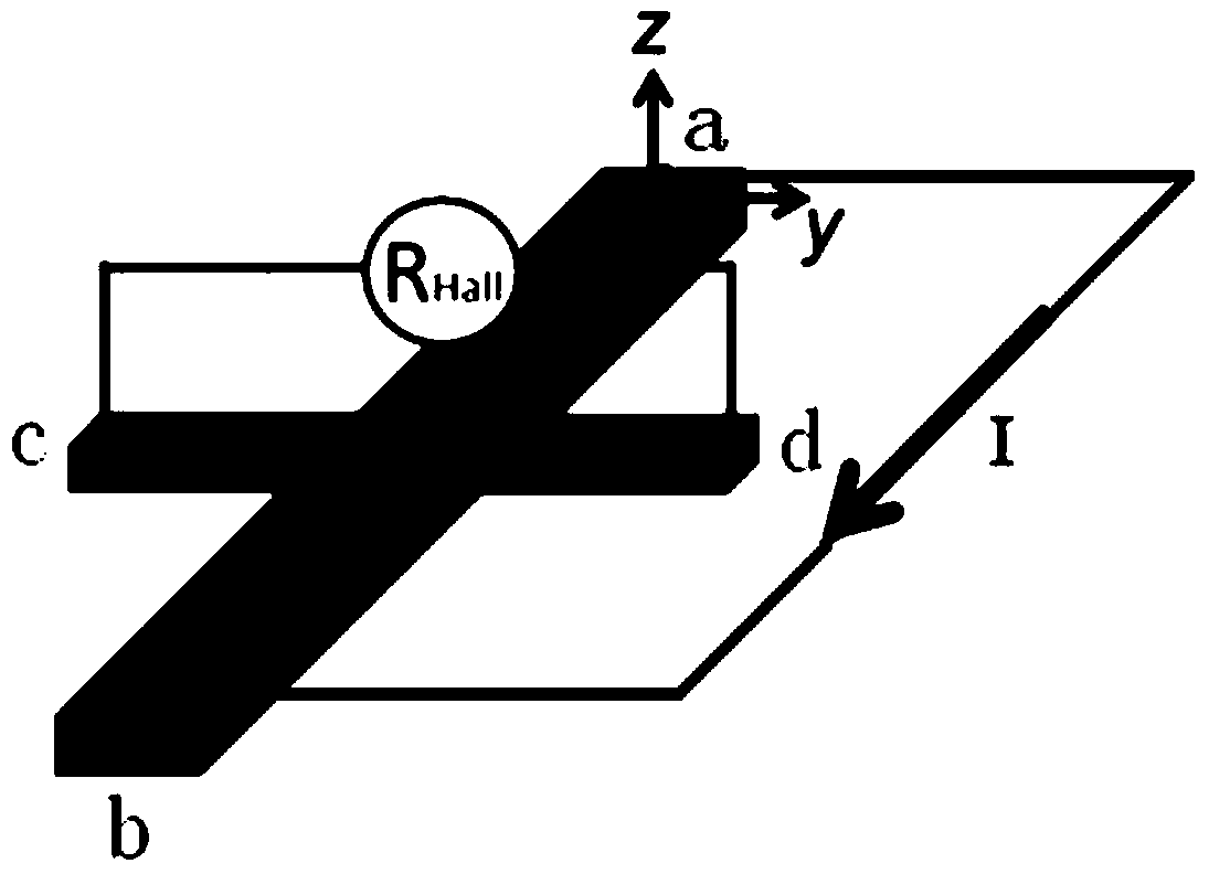
[0026] 2) if figure 2 As shown, the multilayer film structure obtained in step 1) is processed into a cross-shaped structure by using processes such as ultraviolet exposure and argon ion etching. The area of ​​the rectangle where the cross-shaped structure is located is 500×300 μm 2 ~1000×600μm 2 , the area of ​​the cross-overlapped part in the center of the cross-shaped structure is 5×3 μm 2 ~40×30μm 2 .

[0027] Such as figure 2 As shown, the first to fourth endpoints of the magnetic field detector based on the vertical exchange coupling of the present i...

Embodiment 1

[0048] Example 1: Preparation of Si / SiO from bottom to top 2 / [Pt / Co] 2 / IrMn / Pt magnetic field detector, which specifically includes:

[0049] 1) Using magnetron sputtering method, on Si / SiO 2 On the substrate 1, the Pt bottom electrode 2, [Pt / Co] 2 The ferromagnetic layer 3, the IrMn non-magnetic layer 4 and the Pt top electrode 5 form a multilayer film structure.

[0050] Among them, Si / SiO 2 SiO in substrate 1 2 The thickness of the layer is 200 to 400 nm. [Pt / Co] 2 In the ferromagnetic layer 2, the thickness of the Pt layer was 1 nm, and the thickness of the Co layer was 0.5 nm. The thickness of the IrMn nonmagnetic layer 3 is 6 nm to 20 nm, preferably 8 nm.

[0051] 2) Process the multilayer film structure into a cross-shaped structure by using ultraviolet exposure and argon ion etching. The area of ​​the rectangle where the cross-shaped structure is located is 500×300 μm 2 ~1000×600μm 2 , the area of ​​the cross-overlapped part in the center of the cross-shape...

Embodiment 2

[0062] Example 2: Preparation of a magnetic field detector of MgO / CoFeB / FeMn / Pt from bottom to top

[0063] 1) Using the method of magnetron sputtering, a Pt bottom electrode 2, a CoFeB ferromagnetic layer 3, a FeMn nonmagnetic layer 4 and a Pt top electrode 5 are sequentially deposited on the MgO substrate 1 to obtain a multilayer film structure.

[0064] Wherein, the CoFeB ferromagnetic layer 3 is a perpendicularly magnetized ferromagnetic layer with a thickness of 0.7-1.5 nm, preferably 1.2 nm. The thickness of the FeMn non-magnetic layer 4 is 6-20 nm, preferably 10 nm.

[0065] 2) Process the multilayer film structure into a cross-shaped structure by using ultraviolet exposure and argon ion etching. The area of ​​the rectangle where the cross-shaped structure is located is 500×300 μm 2 ~1000×600μm 2 , the area of ​​the cross-overlapped part in the center of the cross-shaped structure is 5×3 μm 2 ~40×30μm 2 .

[0066] Such as figure 1 As shown, a current is passed bet...


PUM


Abstract

The invention relates to a magnetic field detector based on perpendicular exchange coupling and preparing and use methods of the magnetic field detector. The preparing method of the magnetic field detector comprises the following steps that a magnetron sputtering or electronic beam evaporation method is adopted, so that a bottom electrode, a ferromagnetic layer, a non-magnetic layer and a top electrode are sequentially deposited on a substrate, and a multilayer film structure is obtained; an ultraviolet exposure process and an argon ion etching process are adopted, so that the obtained multilayer film structure is processed into a cross-shaped structure. The prepared magnetic field detector comprises the substrate, the bottom electrode, the ferromagnetic layer, the non-magnetic layer and the top electrode, the substrate is of the cross-shaped structure, and the bottom electrode, the ferromagnetic layer, the non-magnetic layer and the top electrode are sequentially deposited on the substrate and matched with the substrate in shape; the ferromagnetic layer is composed of a perpendicular magnetization film, the non-magnetic layer is composed of an anti-ferromagnetic layer or an oxide layer, and the bottom electrode and the top electrode are both Pt electrodes. The magnetic field detector can be widely applied to the process of magnetic field detection.

Description

technical field [0001] The invention relates to a magnetic field detector and its preparation and use method, in particular to a magnetic field detector based on vertical exchange coupling and its preparation and use method. Background technique [0002] The magnetic transmission test includes using the principles of AHE (Anomalous Hall effect, abnormal Hall effect), PHE (Planar Hall effect, planar Hall effect) and anisotropic magnetoresistance effect to detect the magnetization characteristics of the magnetic system. The magnetic sensor of the corresponding principle can Precise detection of the magnitude and direction of the magnetic field is used in many aspects such as magnetic memory, biosensors, aerospace navigation systems and automatic control systems. PHE sensors are usually made of in-plane magnetized materials, which are easy to obtain a linear response. However, the reduction in the size of PHE sensors will make the magnetization state of the sensitive layer affe...

Claims


Application Information

Patent Timeline
Patent Type & Authority Applications(China)
IPC IPC(8): H01L43/00H01L43/12G01R33/02
Inventor 宋成王钰言潘峰
Owner TSINGHUA UNIV
Why Eureka
Try Eureka