Check patentability & draft patents in minutes with Patsnap Eureka AI!

Galvanic element

Active Publication Date: 2015-10-15
ROBERT BOSCH GMBH
View PDF2 Cites 57 Cited by
  • Summary
  • Abstract
  • Description
  • Claims
  • Application Information

AI Technical Summary

Benefits of technology

The patent describes a new material that can be used in batteries to prevent the movement of fluorine and other reactions that can damage the battery. This material can be coated with carbon or other materials like aluminum oxide or fluoride to protect against these reactions. This results in a battery that has a larger capacity and higher energy density.

Problems solved by technology

Lithium ion cells having a liquid electrolyte are disadvantageous in that under mechanical and thermal stress, the liquid electrolyte component can break down and an overpressure occurs in the cell.
Without corresponding protective measures this can cause the cell to burst or even burn.
The use of a graphite anode as proposed in the existing art is disadvantageous because it has only a low energy density compared with an anode based on lithium metal.
With lithium metal-based anodes in turn, it is more difficult to implement manufacture of a galvanic element because the metallic lithium is highly reactive, and is stable only in completely dry environments.
When electrodes based on lithium metal are used with the known solid lithium ion conductors, the problem furthermore occurs that a high contact resistance occurs between the metallic lithium and the ion conductor, and thus only small ionization currents can flow.
This problem becomes worse once a few charge-discharge cycles have occurred, since lithium ions become dissolved out of the anode upon discharge and the volume of the anode changes as a result.

Method used


Image

  • Galvanic element
  • Galvanic element
  • Galvanic element

Examples


first embodiment

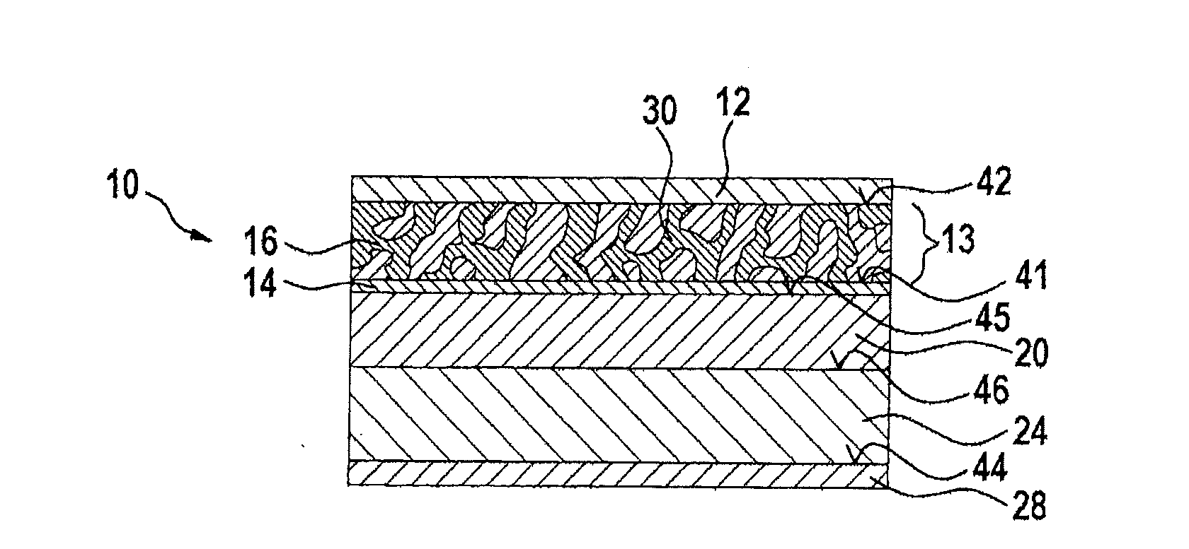
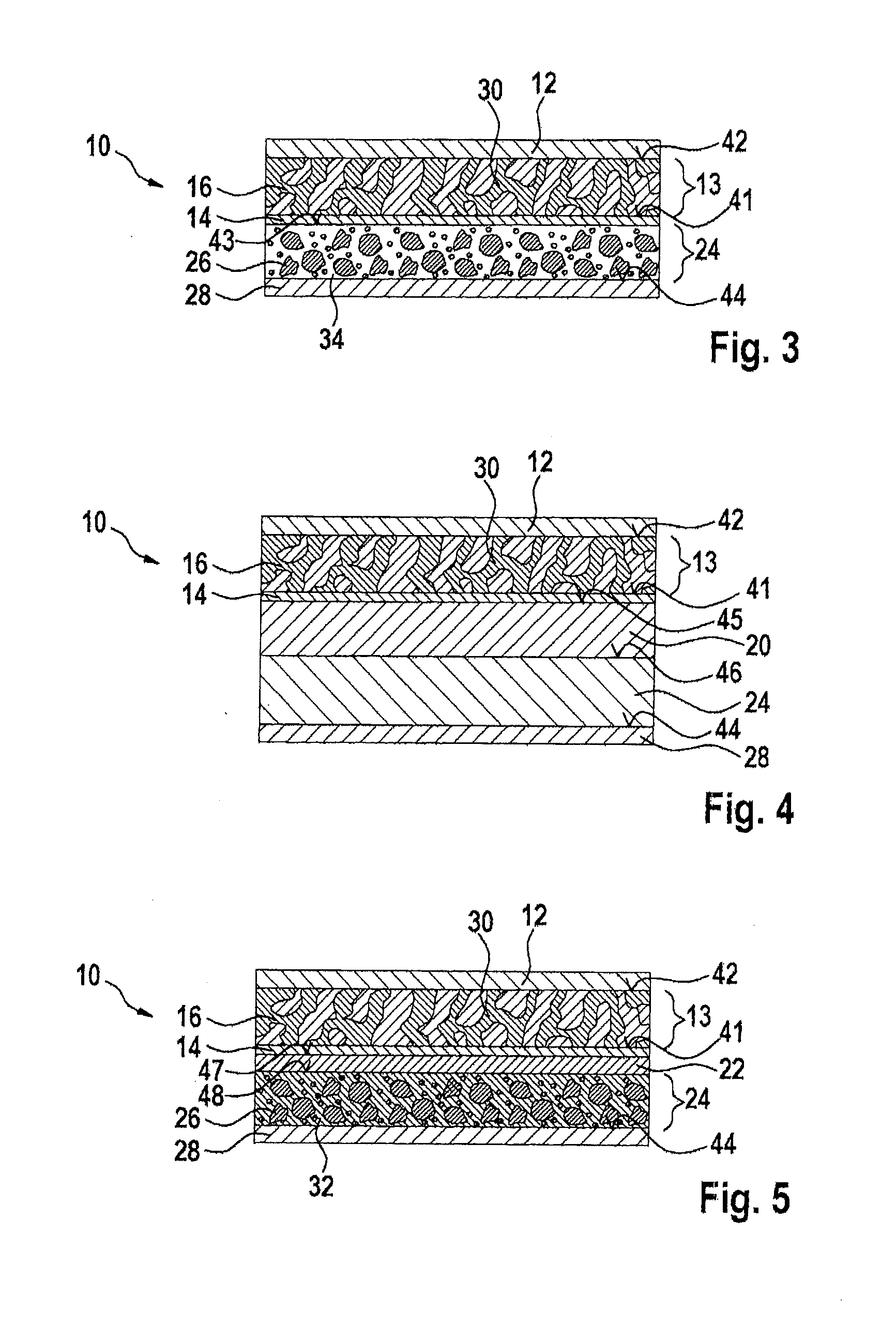
[0054]FIG. 3 depicts a galvanic element 10 according to the present invention.

[0055]Galvanic element 10 encompasses a current collector 12 associated with the anode, an anode 13, a separator 14, as well as a cathode 24 and a current collector 28 associated with the cathode, in that order. A second boundary layer 42 therefore forms between current collector 12 associated with the anode and anode 13, a third boundary layer 43 between separator 14 and cathode 24, and a fourth boundary layer 44 between cathode 24 and current collector 28 associated with the cathode. First boundary layer 41 is located between anode 13 and separator 14.

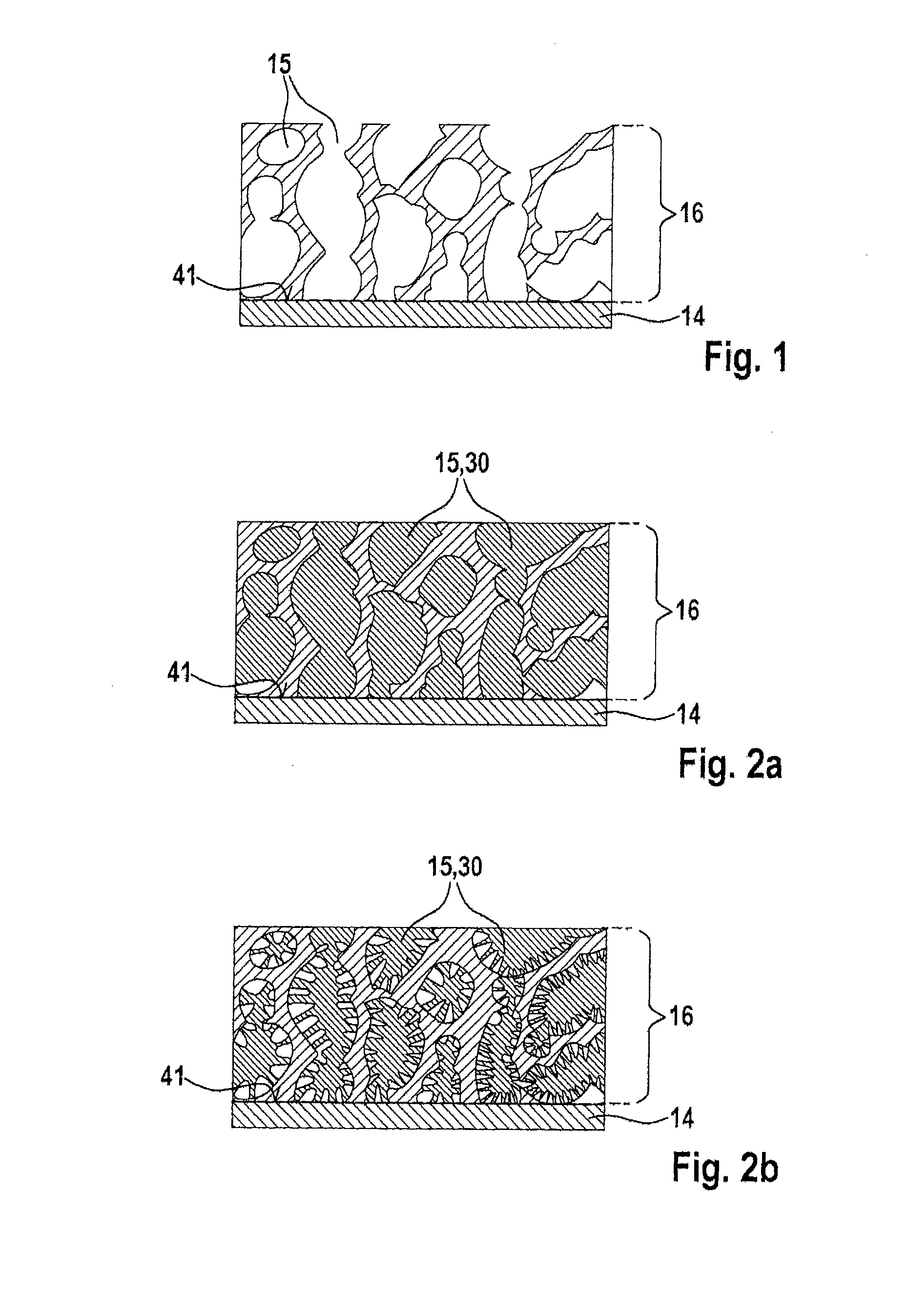
[0056]Anode 13 encompasses an ion-conducting support structure 16 and metallic lithium 30 as an anode active material. The porously configured ion-conducting support structure 16 of anode 13 guarantees that the change in volume is less as compared with the use of a pure lithium film, and that even with a small change in the volume of anode 13, good electric...

third embodiment

[0064]FIG. 5 shows galvanic element 10. Once again galvanic element 10 encompasses current collector 12 associated with the anode, anode 13, separator 14, cathode 24, and current collector 28 associated with the cathode.

[0065]In the embodiment depicted in FIG. 5, cathode 24 has a further ion-conducting support structure 32 as an ion conductor. This further ion-conducting support structure 32 is embodied here as a garnet infiltrated with cathode active material 26, the garnet serving as an ion conductor. It is conceivable for separator 14 also to be embodied as a garnet, the garnets of separator 14 and of further ion-conducting support structure 32 optionally being capable of having different chemical compositions. For example, Li7La3Zr2O12 is suitable as a material for the separator; and Fe-doped and Li-enriched Li4+xTi5O12 is suitable, thanks to its high ion conductivity, for further ion-conducting support structure 32.

[0066]The cathode can furthermore encompass additives to improv...


PUM


Abstract

A galvanic element includes the following elements in the order listed: a current collector associated with an anode; the anode; an ion-conducting separator in the form of a continuous layer; a cathode; and a current collector associated with the cathode. The anode encompasses an ion-conducting support structure, and both the ion-conducting support structure and the separator encompasses an ion-conducting material. The ion-conducing support structure is porous.

Description

BACKGROUND OF THE INVENTION[0001]1. Field Of The Invention[0002]The present invention relates to a galvanic element encompassing a current collector associated with the anode, an anode, a separator, a cathode, and a current collector associated with the cathode. The invention further relates to a battery cell encompassing a galvanic element of this kind, and to a battery encompassing multiple such battery cells.[0003]2. Description Of The Related Art[0004]Lithium ion batteries are notable inter alia for a very high specific energy and extremely low self-discharge. Lithium ion cells possess at least one positive and at least one negative electrode (cathode or anode); lithium ions migrate from one electrode to the other electrode as the battery charges and discharges. A so-called “lithium ion conductor” is necessary in order to transport the lithium ions. In lithium ion cells used at present, which are utilized e.g. in the consumer sector (mobile telephone, MP3 player, etc.) or as ene...

Claims


Application Information

Patent Timeline
IPC IPC(8): H01M10/0562H01M10/0525H01M10/0565
CPCH01M10/0562H01M10/0525H01M10/0565H01M4/13H01M10/052H01M10/058Y02E60/10Y02T10/70
Inventor ENGEL, CHRISTINEBUTZIN, MICHAELKERKAMM, INGO
Owner ROBERT BOSCH GMBH
Features
  • R&D
  • Intellectual Property
  • Life Sciences
  • Materials
  • Tech Scout
  • Unparalleled Data Quality
  • Higher Quality Content
  • 60% Fewer Hallucinations
Learn More