
Container scanning system

a scanning system and container technology, applied in the field of container scanning system, can solve the problems of affecting the overall performance of the container terminal, slowed container, negative impact on the performance of the container terminal, etc., and achieves the effect of improving the overall performance of the terminal, less inspection and maintenance, and increasing the amount of moves per hour

Active Publication Date: 2015-10-15
CAMCO TECH NV
View PDF8 Cites 14 Cited by
  • Summary
  • Abstract
  • Description
  • Claims
  • Application Information

AI Technical Summary

Benefits of technology

The invention is a camera / sensor unit that is mounted on a crane and can move along a rail to scan containers at different positions. This improves the performance of the terminal and reduces delay in information retrieval. It is particularly useful for new or next generation cranes that can operate at different heights. The camera / sensor unit can be easily moved to a service position for easy access, simplifying maintenance.

Problems solved by technology

Firstly, the container identification becomes available late in the container handling process.
Secondly, the sill beam solution negatively impacts the performance of a container terminal, typically expressed or measured as the amount of moves a crane can make per hour.
Since the spreader has to move the container through a fixed window where the cameras are able to scan the container identification, the process of loading / unloading a container is slowed down, which negatively impacts the overall performance of the container terminal.
Thirdly, the sill beam solution is expensive in maintenance since it requires plural cameras.
Since these cameras are operating in difficult conditions resulting from the presence of wind and water in port or railway areas, their lifetime is limited and maintenance requirements are high.
Plural cameras mounted on the sill beams consequently increase the installation and operational costs for the container terminal operator.
Further disadvantageously, front-sides and rear-sides of the containers cannot be scanned in the sill beam solution.
In case the container identification or other useful information such as the IMDG code or seal is marked on or attached to a front-side or rear-side of the container, the sill beam mounted cameras cannot be used.
Such additional cameras however would further increase the installation and maintenance costs for the terminal operator and would further slow down the container handling process since the spreader would have to move the container(s) through a second scan window at a typical height of 13 to 16 meter.
Such solution however requires a dedicated type of crane with rotating flywheel and therefore is not applicable to installed cranes that lack such flywheel.
The maintenance or reparation of electronics or components that operate at such heights will become even more difficult, in particular in harbours where the environmental conditions of wind and water are hard.
Moreover, the availability of boom trucks that can be used for maintenance purposes and can reach heights above 30 meters is scarce.
Although the container scanning system known from WO 2009 / 052854 aims at scanning the container short sides—see WO 2009 / 052854, page 2, line 31 to page 3, line 2—and the presence of IMO placards, the door type, door direction, condition of door seal—see page 9, lines 27-32—the system known from WO 2009 / 052854 is still disadvantageous for several reasons.
Firstly, WO 2009 / 052854 fails to describe how the cameras are made movable along the vertical supports or horizontal beams of the crane.
Such implementations that make use of cables or movable arms however poorly perform in hard environmental conditions resulting from the presence of wind, water and salt in port or railway areas.
Straightforward implementations with movable cameras in other words require regular inspection and maintenance as a result of which their downtime and operational costs are high.
Secondly, the system known from WO 2009 / 052854 does not allow to scan containers that are moved along an optimal path.
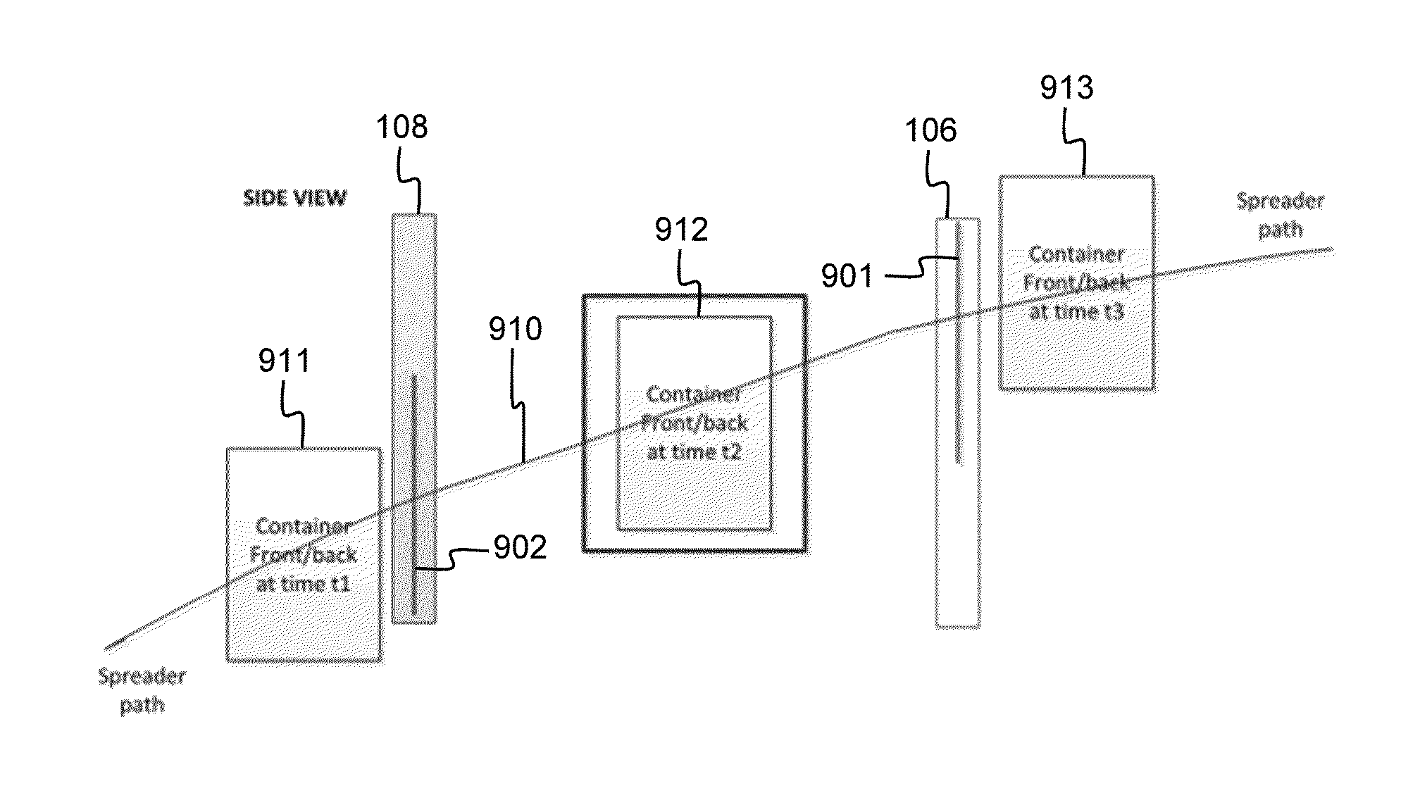
As a result of these differences in nature of the optimal paths followed by different containers, merely using the container position and speed to control the position of the camera / sensor is insufficient to guarantee a successful scan.
The system known from WO 2009 / 052854 consequently can only make successful scans when the crane is controlled to deviate from the optimal path as a result of which unloading / loading containers becomes slower and the overall performance of the crane is reduced.
The system hence has clear technical limitations that can only be resolved at the cost of more cameras / sensors, and the inherent corresponding cost of increased maintenance and downtime.

Method used


Image

  • Container scanning system
  • Container scanning system
  • Container scanning system

Examples


Embodiment Construction

)

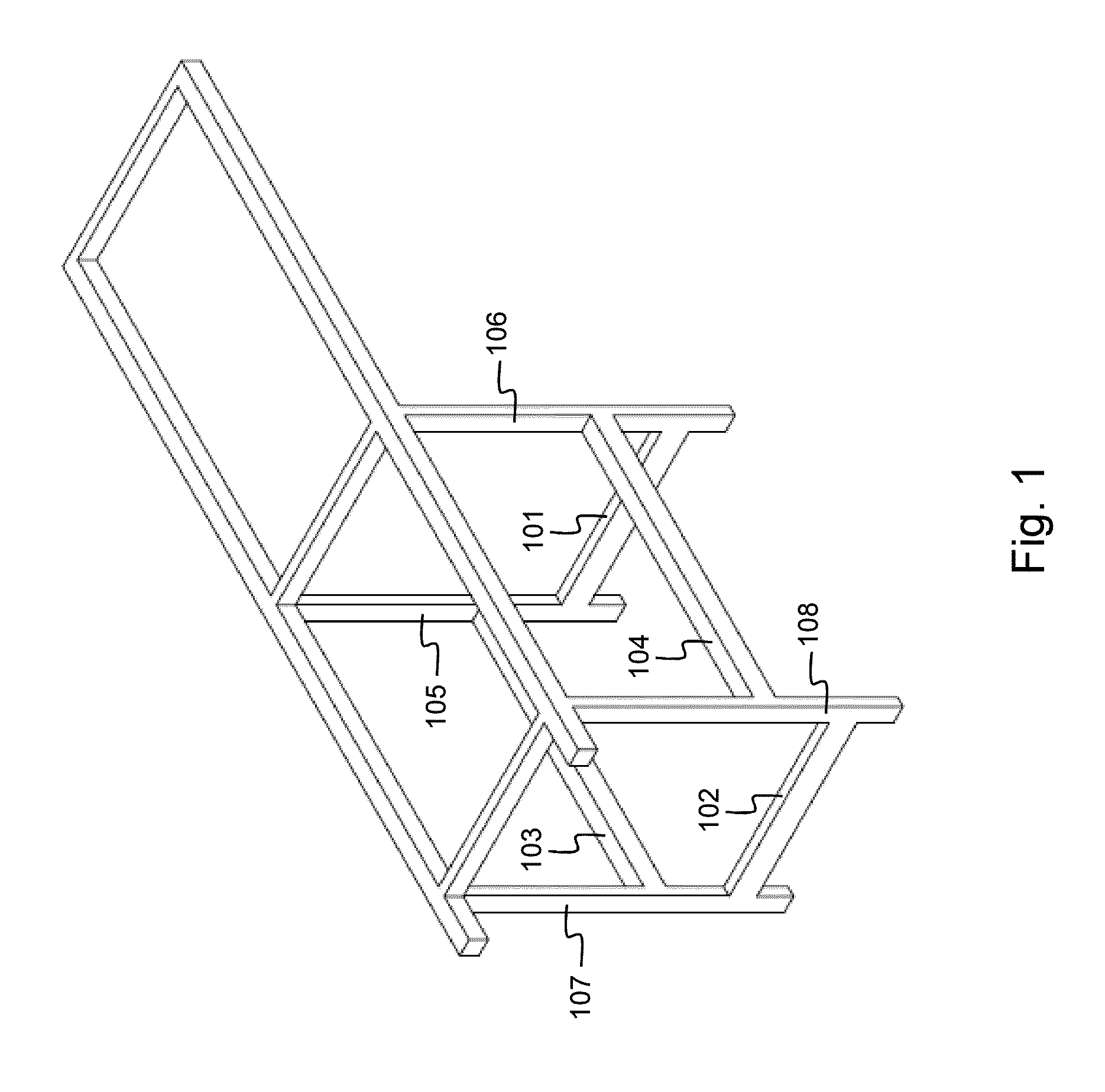
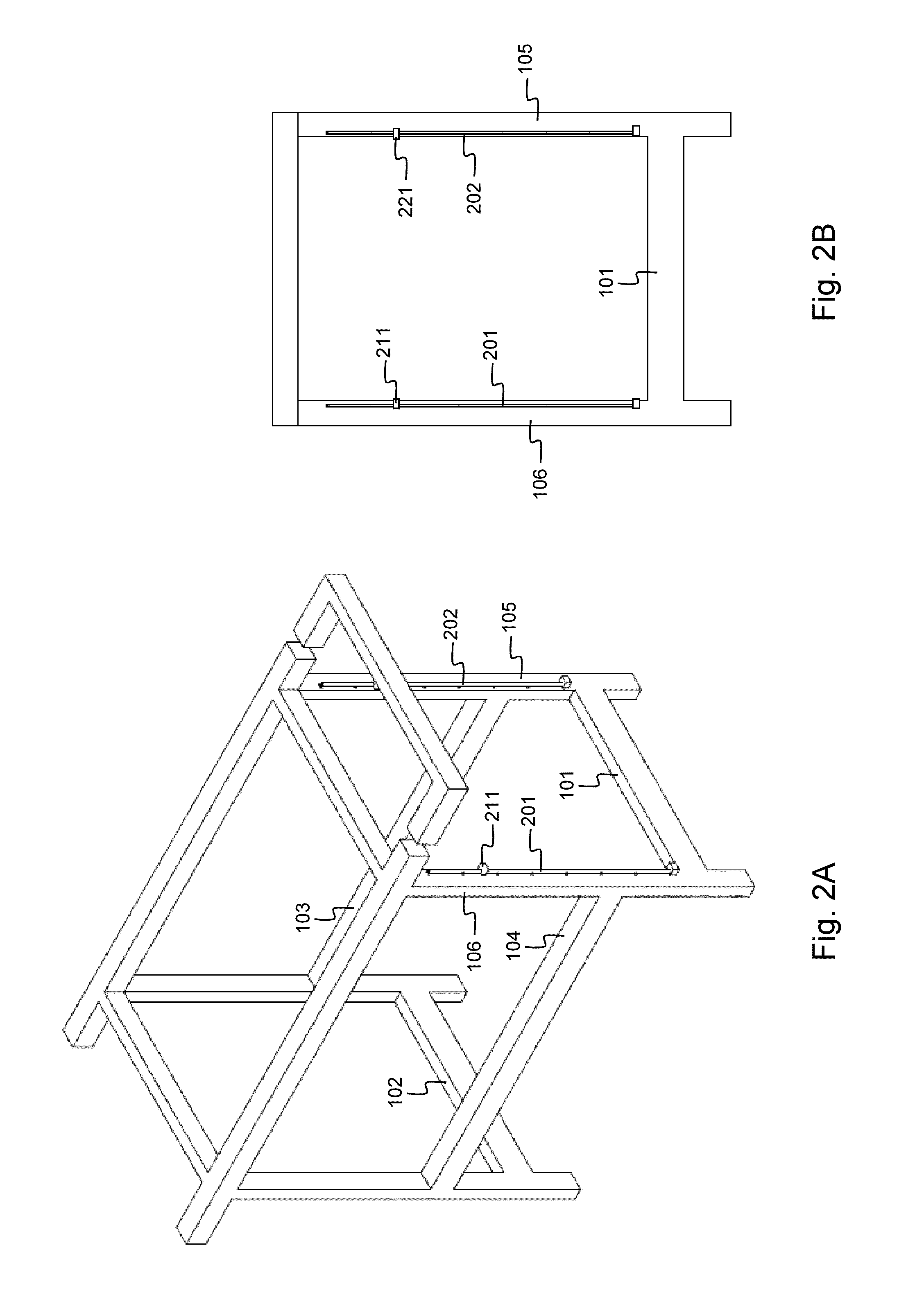
[0089]FIG. 1 shows a crane model that is suitable for deployment of the current invention. Such crane typically has two horizontal sill beams 101 and 102 that are located at a height of 6 meters and two horizontal portal beams 103 and 104 that are located at a height of 13 to 16 meters. The portal beams 103 and 104 are oriented parallel to the crane's boom whereas the sill beams 101 and 102 are oriented perpendicular thereto. Along the crane's boom, a spreader is moving to carry and transfer containers, e.g. from a ship to a storage quay, a train, or a truck, or vice versa. The crane further has four vertical supports of which 105 and 106 represent the sea-side supports and 107 and 108 represent the land-side supports. Such crane is used in ports or railway areas as a result of which the crane is typically designed to have an operational wind load of 25 m / s, to have a breakdown wind load of 50 m / s, to function within a temperature range from −20° C. up to 50° C., and at a humidity ...


PUM


Abstract

A container scanning system comprises a rail, a camera / sensor unit and a control unit. The rail is mounted on a support or beam of a container handling crane. The camera / sensor unit is movably mounted along the rail. The camera / sensor unit comprises a camera and / or a sensor for scanning the exterior surface of a container. The control unit is operationally coupled to the camera / sensor unit. The control unit is able to obtain position information indicative for the operational position of the container handling crane, and the control unit is adapted to control movement of the camera / sensor unit along the rail in function of the position information. The rail contains space for wiring for power feeding the camera / sensor unit.

Description

FIELD OF THE INVENTION[0001]The present invention generally relates to a container scanning system, i.e. camera-based or sensor-based recognition and reading of an item or simply detecting the presence of an item by scanning the exterior surface of cargo containers that are transferred by a container handling crane. The item can be a container identification, a class identification, an IMDG code or International Maritime Dangerous Goods code, a seal, etc. The invention is applicable to different types of cranes that handle cargo containers in port or railway areas like for instance ship-to-shore or STS cranes, i.e. semi-automatic cranes that load containers onto a ship or unload containers from a ship under supervisory control of an operator, rail mounted gantry or RMG cranes used for stacking containers in a storage area of the container terminal, rubber tired gantry or RTG cranes used for stacking containers in a storage area of a container terminal, automatic rail mounted gantry ...

Claims


Application Information

Patent Timeline
Patent Type & Authority Applications(United States)
IPC IPC(8): H04N5/225H04N7/18
CPCH04N7/18H04N5/2252B66C13/46B66C19/002H04N23/51
Inventor DE GEETER, JEF SIMON GASTONBOSSENS, JAN AMANDUS MICHEL MARIA
Owner CAMCO TECH NV
Learn More