
Driving tool

a driving tool and electric current technology, applied in the direction of motor/generator/converter stopper, dynamo-electric converter control, instruments, etc., can solve the problems of unnecessary electric current and unnecessary consumption of driving tools, and achieve the effect of reducing current consumption, reducing electric current consumption, and saving energy

Active Publication Date: 2015-10-22
MAKITA CORP
View PDF29 Cites 34 Cited by
  • Summary
  • Abstract
  • Description
  • Claims
  • Application Information

AI Technical Summary

Benefits of technology

The present patent is about techniques for reducing the electric current consumption of power tools, such as driving tools. The invention is based on the fact that when the motor of a tool is not in use, there is no need to keep the entire tool in a high-energy consumption mode. The invention proposes a mode that reduces current consumption by switching to a reduced current mode based on indicators of motor operation, such as the state of the trigger switch and the contact-arm switch. This mode is preferably switched to when the motor is not operating, but it can also be switched when the trigger or contact-arm switch is in the ON state. By reducing current consumption in this way, the battery life of the tool can be extended, and the need for recharging is reduced. The invention also suggests ways to further improve the efficiency of the reduced current mode, such as by setting the electric-current-supply control unit to a sleep state / mode and detecting the state of the trigger and contact-arm switches. Overall, the invention provides techniques for reducing the electric current consumption of power tools and improving their efficiency.

Problems solved by technology

Consequently, in the above-described known driving tool, when the driving tool is not performing a driving operation, unnecessary electric current will be supplied to the controller circuit.
As a result, the driving tool will consume an unnecessarily large amount of electric current.

Method used


Image

  • Driving tool
  • Driving tool
  • Driving tool

Examples


Embodiment Construction

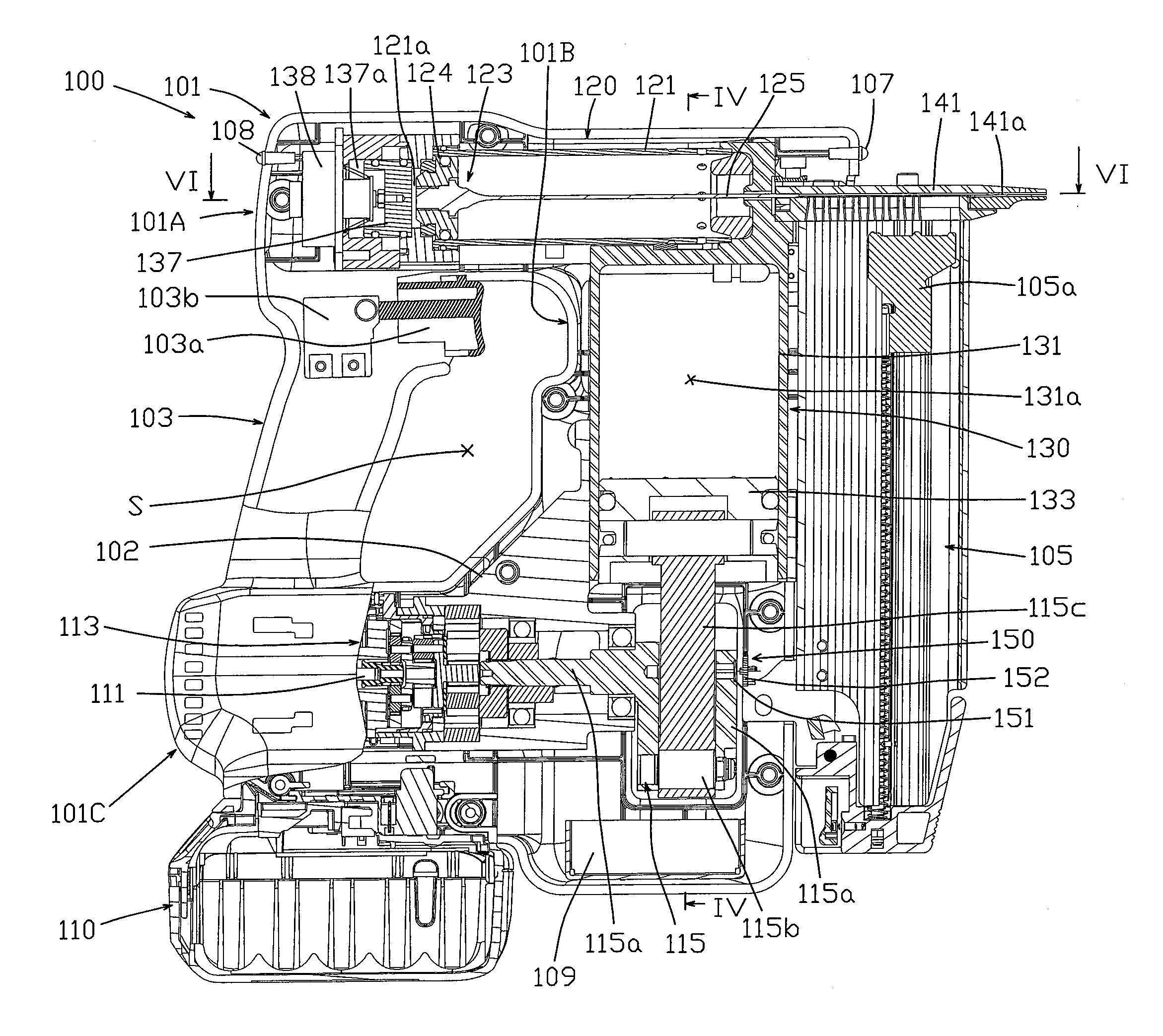
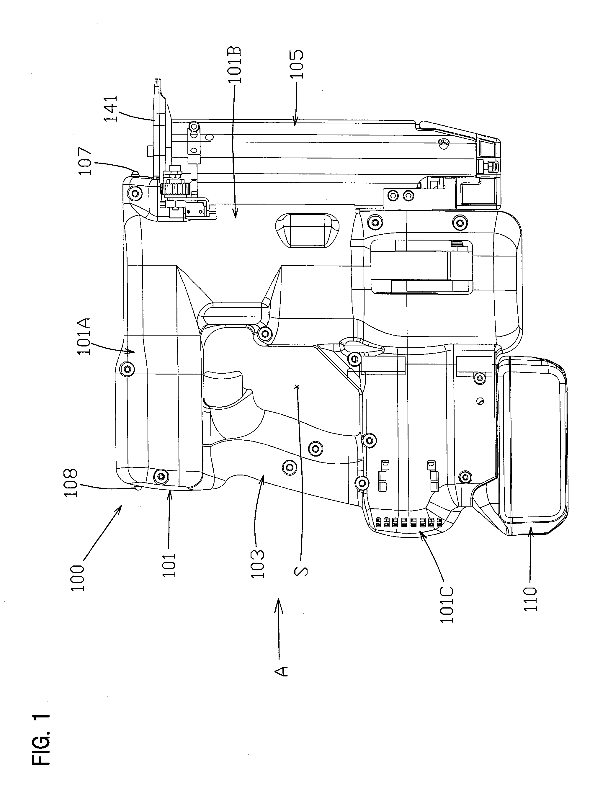
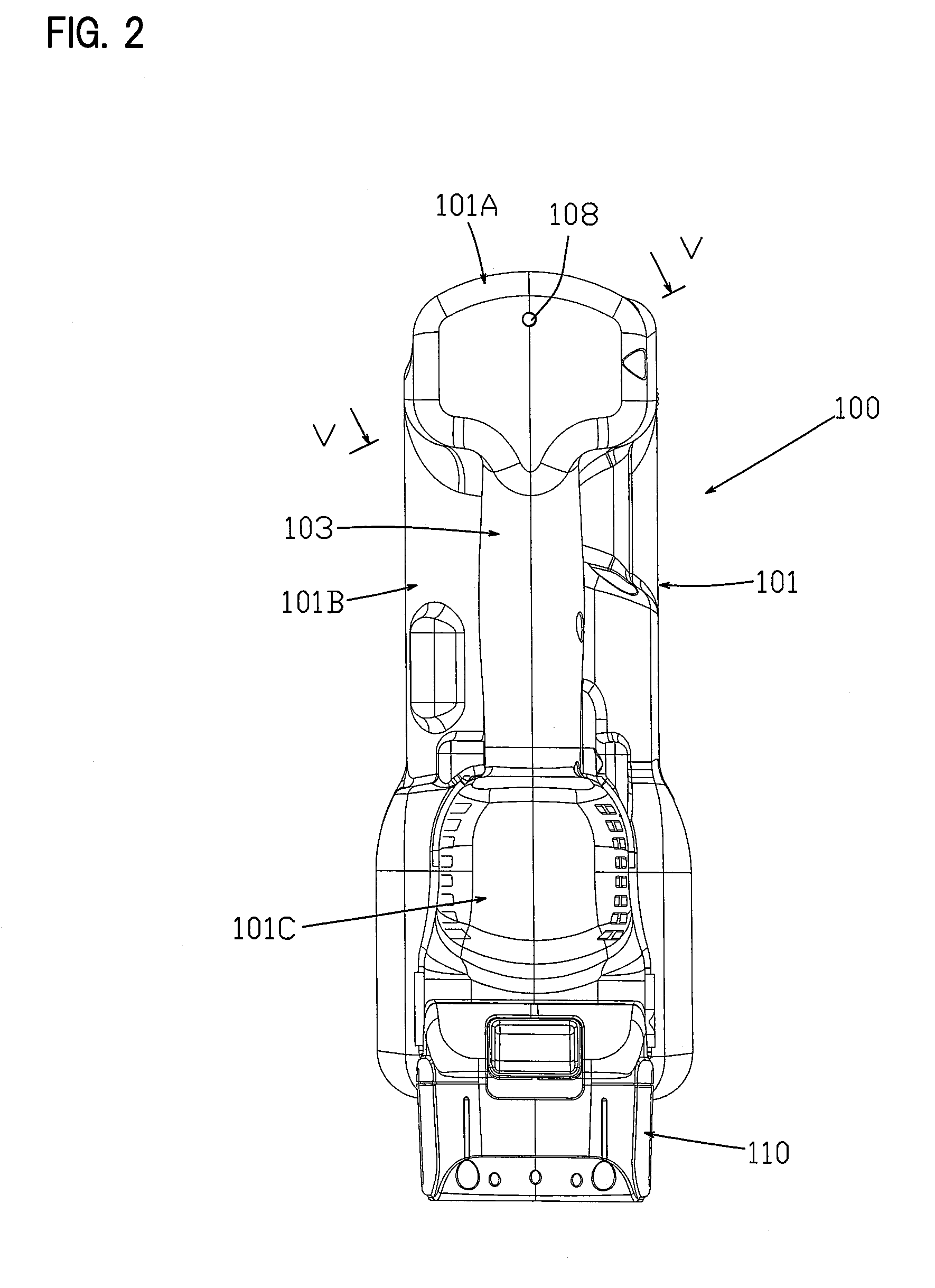
[0033]A representative embodiment of the present disclosure will be explained below, with reference to FIG. 1 through FIG. 8. The present embodiment is explained using an electro-pneumatic nailer as one non-limiting example of a driving tool according to the present disclosure. As shown in the overall views of FIG. 1 and FIG. 2, a nailer (nail gun) 100 may principally comprise a main-body housing 101 and a magazine 105. The main-body housing 101 is defined as a tool main body and forms an outer wall (shell) of the nailer 100. The magazine 105 is loaded with nails (not illustrated), which serve as driven articles that are to be driven into a workpiece. The main-body housing 101 is formed by joining together a pair of substantially symmetrical left and right housings. The main-body housing 101 integrally comprises a handle (handle part) 103, a driving-mechanism housing part 101A, a compression-apparatus housing part 101B, and a motor-housing part 101C.

[0034]The handle part 103, the dr...


PUM

PropertyMeasurementUnit
crank angleaaaaaaaaaa

Abstract

A driving tool, such as a nailer, includes an electric motor, a crank mechanism driven by the electric motor, and a control apparatus for driving the electric motor. A crank-angle detection or calculation unit (109E) detects the crank angle of the crank mechanism or the motor in order to detect the operation state of the electric motor and a stopped time period of the motor is calculated from the crank angle. A sleep-control unit (109A) switches the driving tool between a sleep mode and a drive-enabled mode. If the stopped time period of the electric motor exceeds a prescribed time period, then the sleep-control unit (109A) switches the driving tool to the sleep mode. In the sleep mode, the electric current supplied to one or more of the control units constituting the control apparatus is reduced or cut off, thereby reducing the power consumption of the driving tool.

Description

CROSS-REFERENCE TO RELATED APPLICATION[0001]The present application claims priority to Japanese patent application serial number 2014-084678 filed on Apr. 16, 2014, the contents of which are incorporated fully herein by reference.TECHNICAL FIELD[0002]The present invention generally relates to a driving tool that drives a driven article, such as a fastener, into a workpiece.BACKGROUND ART[0003]A driving tool that drives a driven article (e.g., a fastener) into a workpiece is described in U.S. Pat. No. 8,079,504. In the aforementioned driving tool, compressed air generated by a first piston inside a first cylinder is supplied to a second cylinder. This compressed air causes a second piston to move within the second cylinder and to thereby forcibly strike the driven article, such that the driven article is driven toward and into the workpiece. In addition, this driving tool comprises a sensor that detects the position of the first piston in the operation cycle in which the driven artic...

Claims


Application Information

Patent Timeline
Patent Type & Authority Applications(United States)
IPC IPC(8): B25C1/06B25C1/00H02P3/08
CPCB25C1/06B25C1/008H02P3/08B25C1/04
Inventor KATO, ITSUKU
Owner MAKITA CORP
Learn More