Multifunctional erosion protection strip

a multi-functional, erosion-protection technology, applied in the field of airfoil articles, can solve the problems of increasing fuel consumption, increasing fuel burn, and generally lacking sufficient and effective erosion-protection functionality of the edges, and achieves the effects of low weight, cost-effectiveness, and low cos

Active Publication Date: 2015-10-22
SAAB AB
View PDF4 Cites 16 Cited by
  • Summary
  • Abstract
  • Description
  • Claims
  • Application Information

AI Technical Summary

Benefits of technology

[0076]In such way is achieved that an airfoil article cost-effective can be replaced at the same time as the airfoil article is of low weight, is erosion protected, and serve as a platform for several functions, such as plasma generator system, said anti-/de-icing system, said lightning conductor system, etc....

Problems solved by technology

However, such leading edges generally lack sufficient and effective erosion protection functionality that supports laminar airflow.
The airfoil skins of modern aircraft of today are made of composite materials (such as glass fiber or carbon fiber reinforced epoxy), wherein the aerodynamic surface (of the prior art airfoil stagnation point) is relatively soft and rain erosion may damage the surface accordingly so that unwanted turbulence of the airflow occurs (which negative...

Method used


Image

  • Multifunctional erosion protection strip
  • Multifunctional erosion protection strip
  • Multifunctional erosion protection strip

Examples


Embodiment Construction

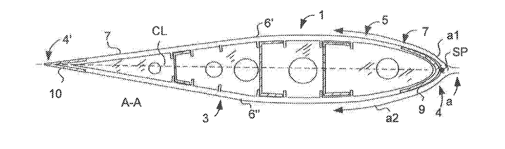
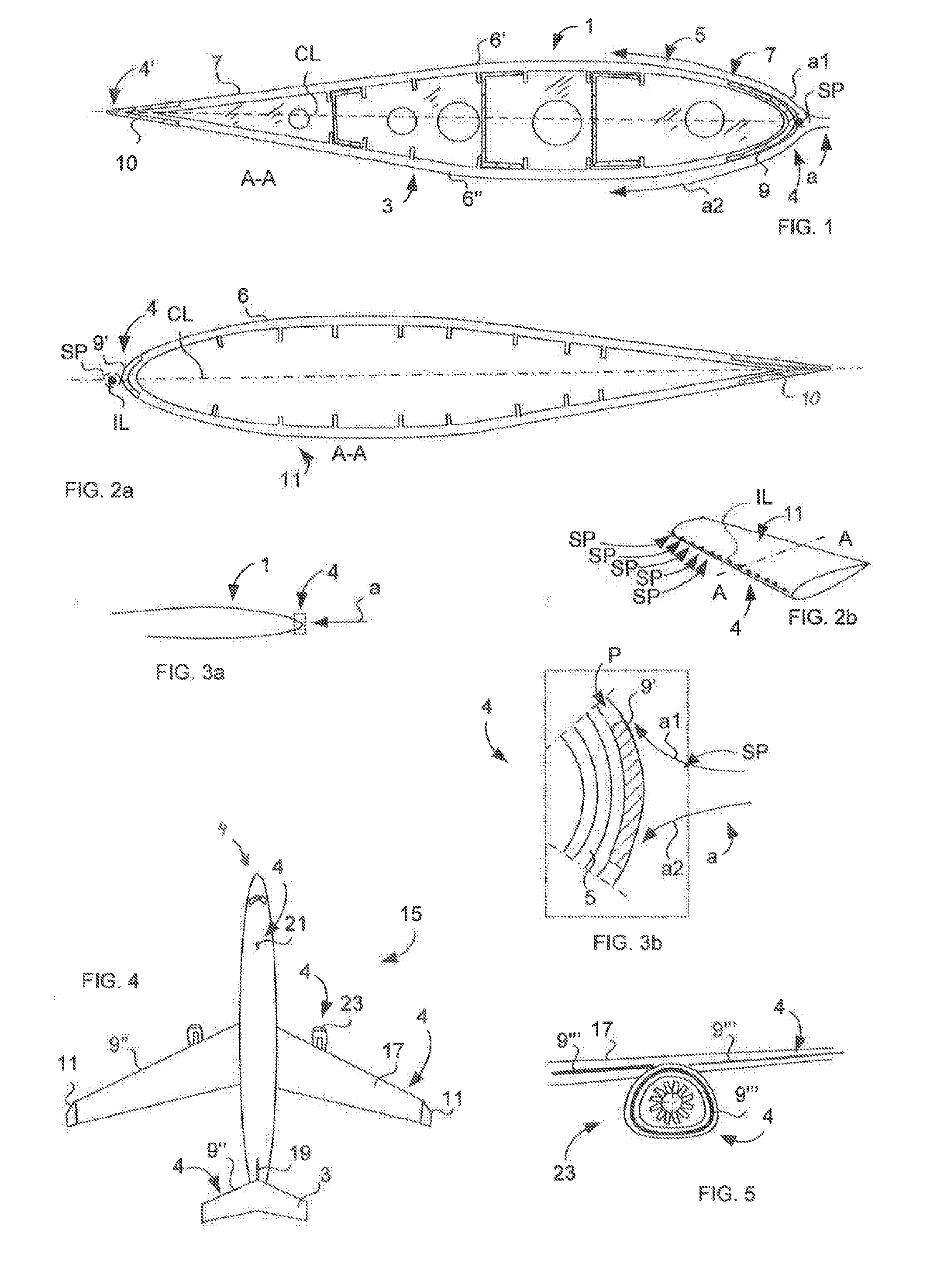
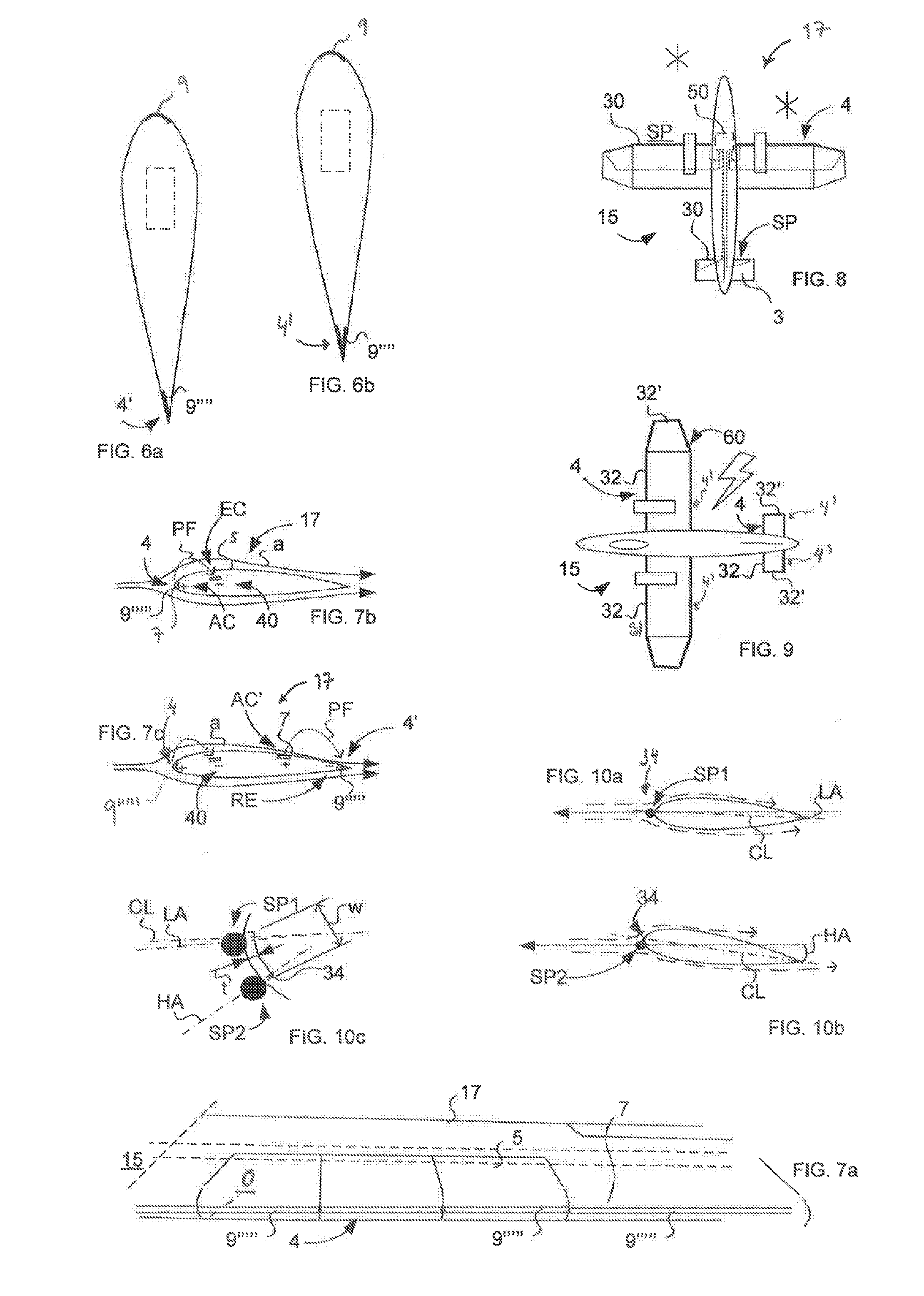
[0111]Hereinafter, embodiments of the present invention will be described in detail with reference to the accompanying drawings, wherein for the sake of clarity and understanding of the invention some details of no importance are deleted from the drawings. Moreover, the drawings shall not be considered drawn to scale as some features may be exaggerated in order to more clearly illustrate the invention. Although, not illustrated in the figures of the present invention is also valid for a swept wing.

[0112]The term “flush arrangement” or “flush mounting” refers to an arrangement and / or mounting of the outer surface of the elongated member, such that it is very precisely positioned in level with the outer surface of the adjacent composite skin (with or without coatings, as applicable) subjected to airflow during use, such as during flight. The outer surface of the elongated member is flush with the adjacent composite skin on both sides in the chord wise direction. This definition of “...


PUM


Abstract

An airfoil article including a composite skin having a first surface and a second surface opposite first surface, forming a leading edge. The leading edge is during use subjected to an airflow meeting the leading edge at stagnation points. The leading edge includes an elongated member. The outer surface of the elongated member is arranged flush with the first surface of the composite skin such that an essentially smooth aerodynamic surface of the leading edge is formed. The elongated member is adapted to serve as an erosion protection of the leading edge and to function as an electrode of a plasma generating system.

Description

TECHNICAL FIELD[0001]The present invention relates to an airfoil article according to the preamble of claim 1.[0002]The present invention also relates to an aircraft comprising at least one airfoil article and a plasma generating system.[0003]Furthermore, the present invention relates to a system for an airfoil article according to the preamble of claim 19.[0004]The invention relates to the aircraft industry. The invention is not limited thereto, but could also be related to activities of airline companies as well. The invention can be used also in automotive engineering, trains, wind power blades etc.BACKGROUND ART[0005]Current aerodynamic technologies for aircraft wings, vertical and horizontal stabilizers etc. include leading edges manufactured of composite material. However, such leading edges generally lack sufficient and effective erosion protection functionality that supports laminar airflow. They comprise steps, gaps, uneven surfaces, fastener protrusions etc. The eroded lea...

Claims


Application Information

Patent Timeline
IPC IPC(8): B64C3/28B64C23/00
CPCB64C23/00B64C3/28B64C2230/12B64D15/12B64D45/02B64D2045/009F01D5/282F05D2240/303Y02T50/10Y02T50/60
Inventor NORDIN, PONTUSSTRINDBERG, GOTE
Owner SAAB AB
Why Eureka
Try Eureka