Internally cooled exhaust gas recirculation system for internal combustion engine and method thereof

a technology of internal combustion engine and exhaust gas recirculation, which is applied in the direction of machines/engines, mechanical equipment, electric control, etc., can solve the problems of loss of volumetric efficiency, no combustion energy, and low engine efficiency, and achieve the effect of eliminating thermodynamic communication

Inactive Publication Date: 2015-10-22
NOSTRUM ENERGY PTE LTD
View PDF7 Cites 17 Cited by
  • Summary
  • Abstract
  • Description
  • Claims
  • Application Information

AI Technical Summary

Benefits of technology

[0015]The direct cooled EGR system of the present invention provides a water injection system that internally cools recirculated exhaust gases inside the EGR loop in the EGR bypass, or in the intake track, or directly within the combustion chamber of the internal combustion engine. The present invention also eliminates the indirect exhaust gases cooling components typically comprising an EGR cooling system including multi-plate, multi-tube, plate or finned heat exchanging devices and components. Further, the present invention eliminates the thermodynamic communication through an exchange media by direct cooling of the recirculated exhaust gases by atomized water.

Problems solved by technology

This reduction in temperature is largely because the returned exhaust gases do not participate in the combustion and thus delivers no combustion energy.
This delay causes control issues which lead to lower engine efficiency.
With i-EGR control is improved, but very high gas temperatures are re-circulated, leading to a loss of volumetric efficiency and a limitation on how much EGR can be achieved prior to knock onset.

Method used


Image

  • Internally cooled exhaust gas recirculation system for internal combustion engine and method thereof
  • Internally cooled exhaust gas recirculation system for internal combustion engine and method thereof
  • Internally cooled exhaust gas recirculation system for internal combustion engine and method thereof

Examples


Embodiment Construction

:

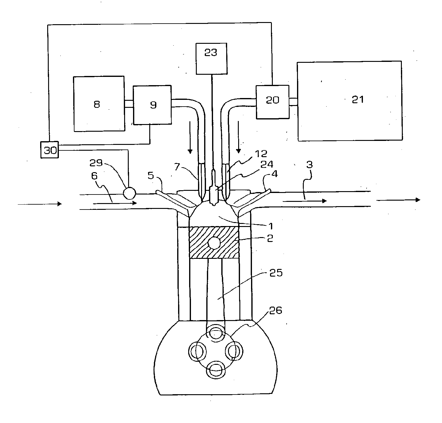
[0028]The present invention provides a four-stroke spark ignition or compression ignition (diesel) internal combustion engine that operates at substantially higher thermodynamic efficiency than conventional engines through the use of lean fuel mixtures, high compression ratios, higher operating temperatures, exhaust gases recirculation (EGR), and water injection in the EGR path, intake manifold or cylinder.

[0029]In the context of the present invention, the term “intake track” refers to any part of the fresh air path between the environment, i.e., the air intake, and the combustion chamber. Thus, the intake track includes the air intake, air inlet, any fresh air conduit, and the intake manifold. In the context of the present invention, the term “exhaust track” refers to any part of the exhaust gases pathway including, for example, the cylinder outlet, the exhaust manifold, any exhaust gases conduit and connections, and may include a muffler and exhaust pipe, venting fumes to the env...


PUM


Abstract

An internal combustion engine is provided equipped with an exhaust gas recirculating (EGR) system and means for internally cooling the exhaust gases by a spray of atomized water into the recirculated exhaust gases prior to ignition. The atomized water spray may be in the intake manifold or directly in the cylinder. The engine may employ spark or compression ignition. The internal combustion engine operates with compression ratios greater than 12:1 and lean air:fuel ratios. Also provided is a method for controlling the amount of exhaust gas recirculated in the engine, and for controlling the amount of water added. The inventive engines have elevated thermodynamic efficiencies and favorable NOx emissions.

Description

CROSS-REFERENCE TO RELATED APPLICATIONS[0001]The instant application claims priority from U.S. Provisional Patent Applications Nos. 61 / 728,516 filed on Nov. 20, 2012, and 61 / 753,719 filed Jan. 17, 2013, the contents of both of which are incorporated herein by reference.FIELD OF THE INVENTION[0002]The present invention relates generally to internal combustion engines. More specifically, the present invention relates to an internal combustion engines with exhaust gases recirculation.BACKGROUND[0003]This invention pertains to internal combustion engines with at least one reciprocating piston that operate with directly cooled exhaust gases recirculation (EGR). The principles set forth herein can be used in both spark-ignition (SI) engines typically operating on gasoline (petrol), natural gas, or ethanol blends, or in compression-ignition (CI) engines typically operating on diesel, biodiesel, JP-8 or other jet fuel variants, kerosene, or heavy oil. This invention is applicable to both no...

Claims


Application Information

Patent Timeline
Patent Type & Authority Applications(United States)
IPC IPC(8): F02M25/07F02B47/02F02B47/08F02M21/08
CPCF02M25/07F02B47/08F02B47/02F02M21/08F02M25/03F02M25/028F02M26/05F02M26/06F02M26/00F02M26/36F02M26/01F02M26/22F02M25/025Y02T10/12
Inventor MULYE, NIRMALSANE, SHRIKRISHNABARROS NETO, OSANAN L.
Owner NOSTRUM ENERGY PTE LTD
Why Eureka
Try Eureka