Wireless inductive power transfer

a technology of inductive power transfer and wireless, which is applied in the direction of inductance, battery data exchange, exchanging data chargers, etc., can solve the problems of inconvenient use, impracticality, and battery use, and achieve the effect of reducing power signal variations and enhancing functionality

Active Publication Date: 2015-10-22
KONINKLJIJKE PHILIPS NV
View PDF2 Cites 18 Cited by
  • Summary
  • Abstract
  • Description
  • Claims
  • Application Information

AI Technical Summary

Benefits of technology

The invention is an improved power transfer system that allows for bidirectional communication. This is done without adding any additional modulation or power signal variations. The system is practical, low complexity, and flexible, making it easy to support bidirectional communication with a power transmitter.

Problems solved by technology

However, this tends to be impractical and requires the user to physically insert connectors or otherwise establish a physical electrical contact.
It also tends to be inconvenient to the user by introducing lengths of wire.
Although, the use of internal batteries may avoid the need for a wired connection to a power supply during use, this only provides a partial solution as the batteries will need recharging (or replacing which is expensive).
The use of batteries may also add substantially to the weight and potentially cost and size of the devices.
However, the approach is restrictive and may not allow the full desired flexibility and support for functions as required.
For example if a power receiver tries to get more than 5 W power from a power transmitter the power transmitter may terminate power transfer resulting in a bad user experience.
As an example of challenges when further developing the Qi standards is that of how to support the desired interaction between power transmitters and power receivers.
However, rather than ignore such messages, it has been found that a number of power transmitters that have been manufactured respond to receiving such messages by aborting any ongoing power transfer.
Thus, existing power transmitters cannot be used with future power receivers using the reserved extension messages.
Accordingly, the further developments of the standard cannot readily utilize the reserved messages.
However, although WO2012 / 049582 may allow some communication from the power transmitter to the power receiver, it may not be optimal in all scenarios.
For example, the added amplitude or frequency modulation may be an undesirable modification to the power signal in some situations.
Also, the approach is based on characteristics only present during initialization and prior to the power transfer, and this may restrict the use in many practical scenarios.
In general, the introduction of a bidirectional link is not trivial and is subject to a large number of difficulties and challenges.
Furthermore, the technical restrictions in terms of e.g. modulation options, power variations, transmission options etc. are very restrictive as they need to fit in with the existing parameters and with regulatory requirements.
Indeed, in some areas regulatory requirements do not allow direct modulation of the power signal.
Although this may be addressed by using a separate communication link, such as e.g. a Bluetooth communication link, this adds complexity and cost to the implementation.
Accordingly, many challenges and difficulties are associated with enhancing a power transfer system such as Qi to include bidirectional communication.
Thus, the introduction of bidirectional communication in power transfer systems, such as Qi systems, is complicated and subject to many restrictions and requirements in order to ensure both efficient power transfer, efficient operation and not least backwards compatibility.

Method used


Image

  • Wireless inductive power transfer
  • Wireless inductive power transfer
  • Wireless inductive power transfer

Examples


example 1

[0177]In this example, the power transmitter 10 is comprised in a wake-up light. The wake-up light is used with a protective sleeve for a hand-held device (e.g. a phone). The sleeve provides wireless charging functionality to the device (e.g. an existing smartphone), and may be sold as an accessory to the wake-up light. In this example, the query message comprises a device identifier, i.e. a message including the device identifier is considered a query message. After completing the initial stage of the power transfer—i.e. the power receiver 105 sending its identification and configuration data—the power receiver 105 waits for a predetermined interval, before it starts to direct the power transmitter 101 to adjust its coil current—i.e. by sending appropriate power control error messages. The power transmitter 101 of the wake-up light charger will recognize the query contained in the identification data for the power receiver 105, and will adjust its coil current to reflect the define...

example 2

[0179]This example uses similar devices as example 1 except that the power receiver 105 is comprised directly in the smartphone. In the example, applications (apps) running on the smartphone can interact with the wireless charging functionality. In this second example, the device identification data is not used to carry the query. However, it is possible for the app running on the smartphone to send a query contained in a Proprietary Packet, i.e. the query message is in the form of a Proprietary Packet. As in the previous example, this query could direct the wake-up light charger to insert a specific modification to processing of power control error messages by the power transmitter 101. Specifically, the query can contain directions on how the power transmitter 101 should interpret the next few power control error messages in a different way—e.g. reverse the sign of the next two power control error messages. An advantage of using Proprietary Packets is that the app can send multipl...

example 3

[0180]In this example, a power receiver 105 seeks to determine whether it is coupled to a power transmitter 101 compliant with a revision / version of the standard which is higher or equal to that of the power receiver 105. In this example, the power transmitter 101 can interpret the version number sent by the power receiver 105 in the initial stage of the power transfer, i.e. the standards version reference forms the query. At the start of the power transfer phase, a power transmitter 101 matching the version, or which complies with a newer version, can insert a signature modification pattern to the responses to the power control error messages, i.e. it can change the coil current in a different way at the start of the power transfer phase. A particular advantage of this approach is that it provides a work-around for the issue of reserved packets being used incorrectly in legacy equipment (and specifically the problem that legacy power transmitters may terminate a power transfer phas...


PUM


Abstract

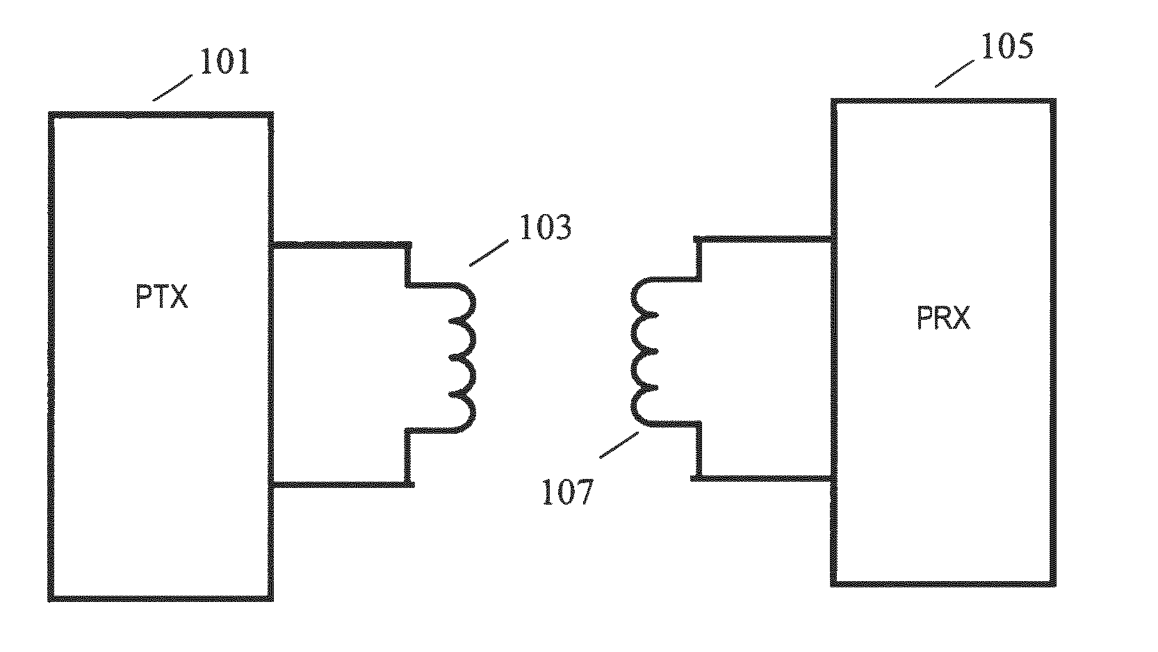
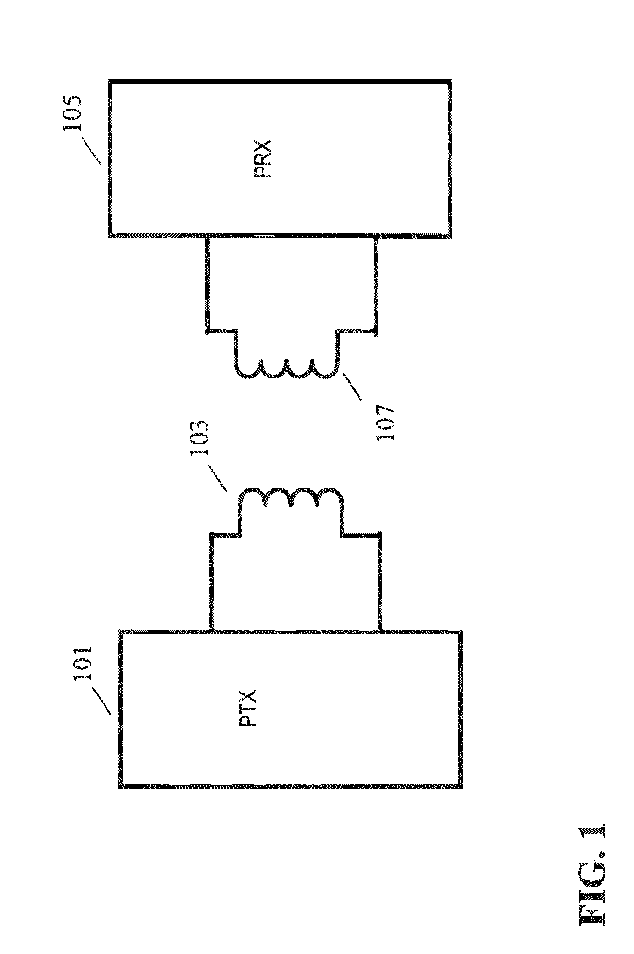
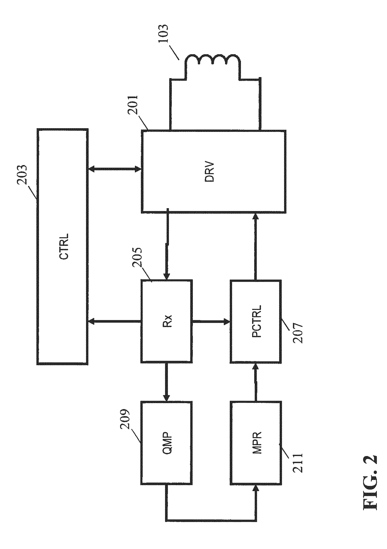
A power transmitter (101) is arranged to transfer power to a power receiver (105) using a wireless inductive power signal. The power transmitter (101) comprises a power signal generator (207) which drives an inductor (103) to provide the power signal to an inductor of the power receiver (105). A power loop control is employed by the power receiver (105) providing power control error messages to the power transmitter (101). The power transmitter (101) comprises a query message processor (209) which can detect a query message received from the power receiver (105) using load modulation of the power signal. A modification processor (211) is arranged to modify a response of the power loop controller to the power control error messages dependent on the query message. The power receiver (105) can detect the modifications to the operation of the power control and thus can interpret this as a response to the query message.

Description

FIELD OF THE INVENTION[0001]The invention relates to inductive power transfer and in particular, but not exclusively, to an inductive power transfer system in accordance with the Qi wireless power transfer standard.BACKGROUND OF THE INVENTION[0002]The number and variety of portable and mobile devices in use have exploded in the last decade. For example, the use of mobile phones, tablets, media players etc. has become ubiquitous. Such devices are generally powered by internal batteries and the typical use scenario often requires recharging of batteries or direct wired powering of the device from an external power supply.[0003]Most present day systems require a wiring and / or explicit electrical contacts to be powered from an external power supply. However, this tends to be impractical and requires the user to physically insert connectors or otherwise establish a physical electrical contact. It also tends to be inconvenient to the user by introducing lengths of wire. Typically, power r...

Claims


Application Information

Patent Timeline
IPC IPC(8): H04B5/00H02J5/00
CPCH02J5/005H04B5/0037H02J50/80H02J50/12H02J7/00034H04B5/72H04B5/79H04B5/26H02J50/10H02J7/00
Inventor STARING, ANTONIUS ADRIAAN MARIAVAN WAGENINGEN, ANDRIES
Owner KONINKLJIJKE PHILIPS NV
Why Eureka
Try Eureka