System and Method for Determining Modulation Control Information and a Reference Signal Design to be Used by a Transmitter Node

a technology of reference signal and control information, which is applied in the field of system and method for determining modulation control information and reference signal design to be used by a transmitter node, can solve the problems of increasing the pilot density, affecting data throughput, and prohibitively high complexity of such a schem

Active Publication Date: 2015-10-22
AIRSPAN IP HOLDCO LLC
View PDF7 Cites 30 Cited by
  • Summary
  • Abstract
  • Description
  • Claims
  • Application Information

AI Technical Summary

Benefits of technology

[0050]In one embodiment, the above described method can be re-performed whenever desired, for example on occurrence of one or more trigger conditions, and can be performed quickly enough to allow the combination of candidate reference signal design and candidate modulation control information that prov

Problems solved by technology

Whilst it is possible to compute the CSI directly from the received signal, utilising the second and in some instances higher order statistics of the signal, the complexity of such a scheme is prohibitively high, requiring long processing periods to guarantee convergence with slow adaptation capabilities, making this scheme unsuitable for rapidly time-varying channels.
However, increasing the pilot density has a detrimental effect on data throughput.
In addition, channel estimation can also be improved by allocating more transmit power to the pilot symbols, but this comes at the expense of decreasing the signal to noise ratio for the data symbols.
Thus, there is a trade-off between the channel estimation accuracy and bandwidth efficiency.
Notwithstanding th

Method used


Image

  • System and Method for Determining Modulation Control Information and a Reference Signal Design to be Used by a Transmitter Node
  • System and Method for Determining Modulation Control Information and a Reference Signal Design to be Used by a Transmitter Node
  • System and Method for Determining Modulation Control Information and a Reference Signal Design to be Used by a Transmitter Node

Examples


Embodiment Construction

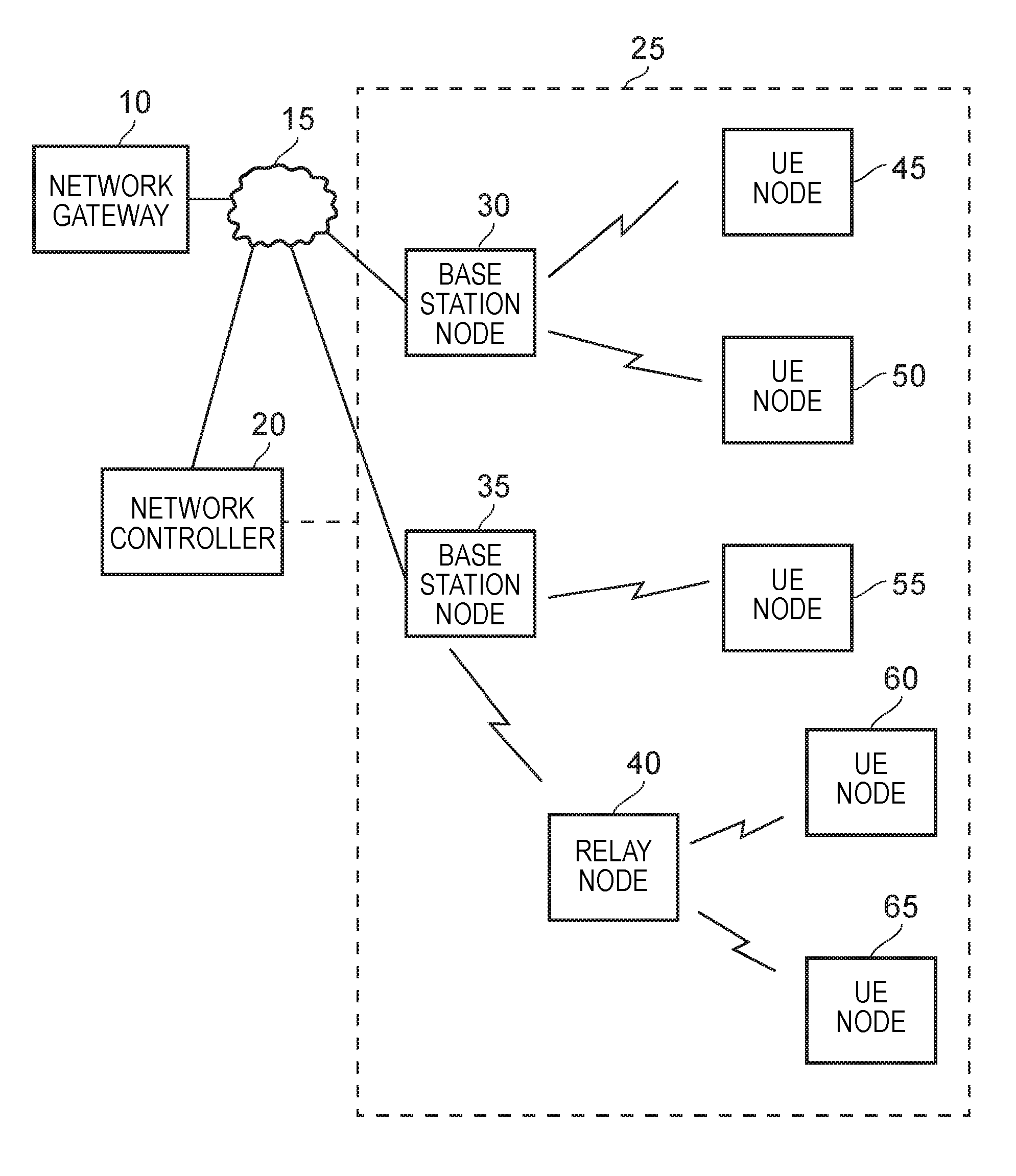
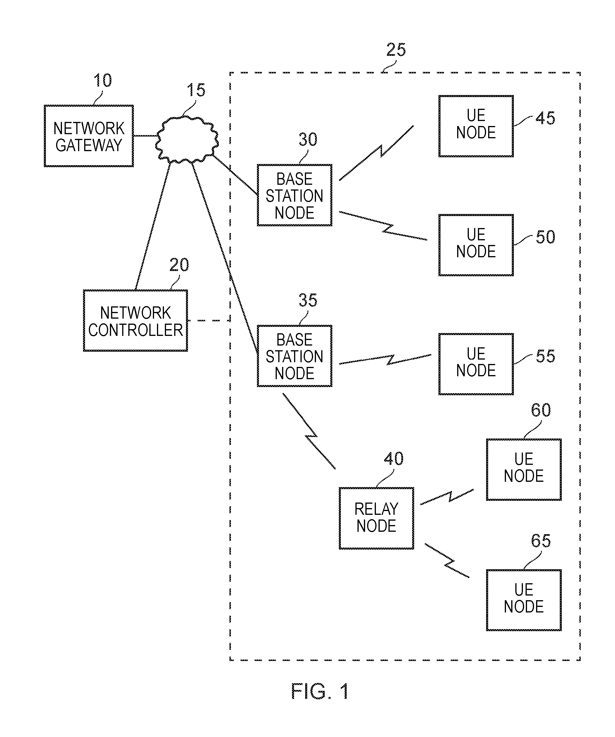
[0068]FIG. 1 schematically illustrates a wireless network in which the techniques of embodiments of the present invention may be employed. As shown, a number of base station nodes 30, 35, 40 are provided to communicate via a wireless air interface with a number of mobile stations / items of end user equipment 45, 50, 55, 60, 65. The items of end user equipment may be mobile or fixed, and any one of a number of known wireless communications protocols may be used to effect the wireless links between the base station nodes and the user equipment nodes.

[0069]As also shown in FIG. 1, one or more of the base station nodes 40 may actually act as a relay node for onward transmission of communications issued by an associated base station node 35, and indeed for relaying back to the base station node 35 signals transmitted by the items of end user equipment 60, 65.

[0070]The base station nodes 30, 35 of the wireless network are typically connected via a communications infrastructure 15 with an a...


PUM


Abstract

A method and system are provided for determining modulation control information and a reference signal design to be used by a transmitter node when generating a transmit signal to transmit from a transmitter (logical antenna) of the transmitter node over a channel of a wireless link to a recipient node. The modulation control information is used by the transmitter node to convert source data into an information bearing signal, and the information bearing signal is combined with a reference signal conforming to the reference signal design in order to produce the transmit signal. The method comprises (a) selecting a candidate reference signal design from a plurality of candidate reference signal designs, (b) determining channel state information for the channel, (c) determining, from the channel state information, signal to noise ratio information for said channel, and (d) for each of a plurality of candidate modulation control information, using the signal to noise ratio information to determine a quality indication for said channel. Steps (a) to (d) are then repeated for each candidate reference signal design in said plurality. Thereafter a winning quality indication is selected from the determined quality indications, and the combination of candidate reference signal design and candidate modulation control information associated with the winning quality indication is then output to the transmitting node. By such an approach, quality indications can be established for each combination of possible reference signal design and possible modulation control information, and hence not only is the inherent channel estimation accuracy achievable using each possible reference signal design considered, but also the data transmission efficiency and robustness to channel effects of each possible modulation control information is also taken into account.

Description

FIELD OF THE INVENTION[0001]The present invention relates to a system and method for determining modulation control information and a reference signal design to be used by a transmitter node when generating a transmit signal to transmit from a transmitter of the transmitter node over a channel of a wireless link to a recipient node.BACKGROUND OF THE INVENTION[0002]Within a wireless network, there will typically be a plurality of nodes that need to communicate with each other, and wireless communications links are established between the various nodes to support such communications. Considering a wireless telecommunications network, for a downlink communication path a transmitter node (for example a base station (BS)) may need to communicate with a plurality of recipient nodes (such as mobile stations(MSs) / items of end user equipment(UEs)). Similarly, for an uplink communication path multiple transmitter nodes (for example MSs / UEs) may need to communicate with a particular recipient ...

Claims


Application Information

Patent Timeline
IPC IPC(8): H04L25/02H04L5/00H04L1/00
CPCH04L25/024H04L1/0009H04L5/0048H04L1/0003H04L1/0006H04L1/0015H04L1/203H04L25/0226
Inventor LOGOTHETIS, ANDREWLYSEJKO, MARTIN
Owner AIRSPAN IP HOLDCO LLC
Why Eureka
Try Eureka