Neural sleeve for neuromuscular stimulation, sensing and recording

a neuromuscular and neuromuscular technology, applied in the field of neuromuscular stimulation, sensing and recording, can solve the problems of not allowing selective stimulation of small muscles segments for fine wrist and finger control, many limitations of current transcutaneous neuromuscular stimulation electrodes (or patches), etc., to achieve the effect of enhancing flexibility and/or durability

Active Publication Date: 2015-10-29
BATTELLE MEMORIAL INST
View PDF1 Cites 36 Cited by
  • Summary
  • Abstract
  • Description
  • Claims
  • Application Information

AI Technical Summary

Benefits of technology

[0019]The reusable sleeve may include a flexible circuit which may include electrodes connected by electrode traces; the electrode traces may house sensors; and the electrode traces may be arranged in a zig-zag pattern to enhance flexibility and / or durability. The sensors may include any combination of pressure sensors; strain gauges; accelerometers; a micro-electro-mechanical system (MEMS) including a 3-axis accelerometer and 3-axis magnetometer; a capacitive sensor including a flexible insulating dielectric layer sandwiched between flexible electrodes; a stretch sensor including a material that changes electrical resistance when stretched or strained; a resonant bend sensor including a resistance-inductance-capacitance (RLC) circuit; a sensor including at least one bladder configured to hold a fluid or air; a fiber optic cable and a measurement tool configured to measure a bend in the fiber optic cable based on a frequency or attenuation change in a signal of the fiber optic cable; and a video motion tracking system configured to track a marker of the reusable sleeve.

Problems solved by technology

Current transcutaneous neuromuscular stimulation electrodes (or patches) present many limitations.
This does not allow selective stimulation of small muscles segments for fine wrist and finger control.

Method used


Image

  • Neural sleeve for neuromuscular stimulation, sensing and recording
  • Neural sleeve for neuromuscular stimulation, sensing and recording
  • Neural sleeve for neuromuscular stimulation, sensing and recording

Examples


Embodiment Construction

[0054]A more complete understanding of the processes and apparatuses disclosed herein can be obtained by reference to the accompanying drawings. These figures are merely schematic representations and are not intended to indicate relative size and dimensions of the assemblies or components thereof.

[0055]Although specific terms are used in the following description for the sake of clarity, these terms are intended to refer only to the particular structure of the embodiments selected for illustration in the drawings, and are not intended to limit the scope of the disclosure. In the drawings and the following description below, it is to be understood that like numeric designations refer to components of like function.

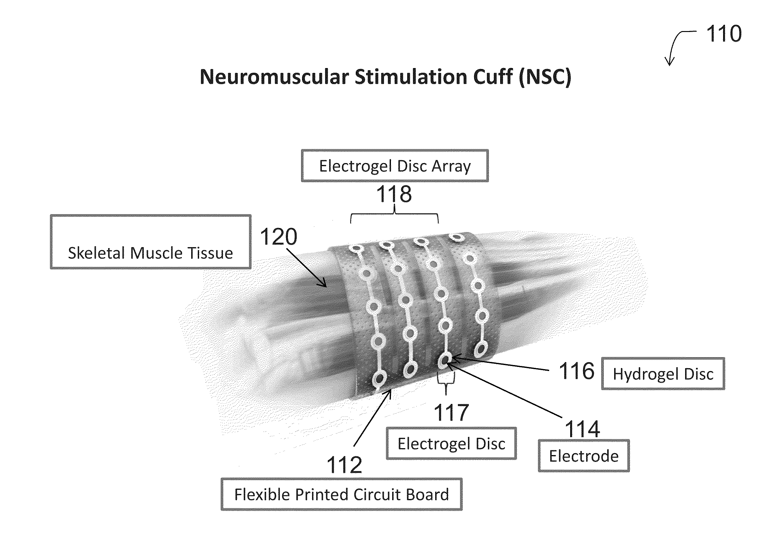
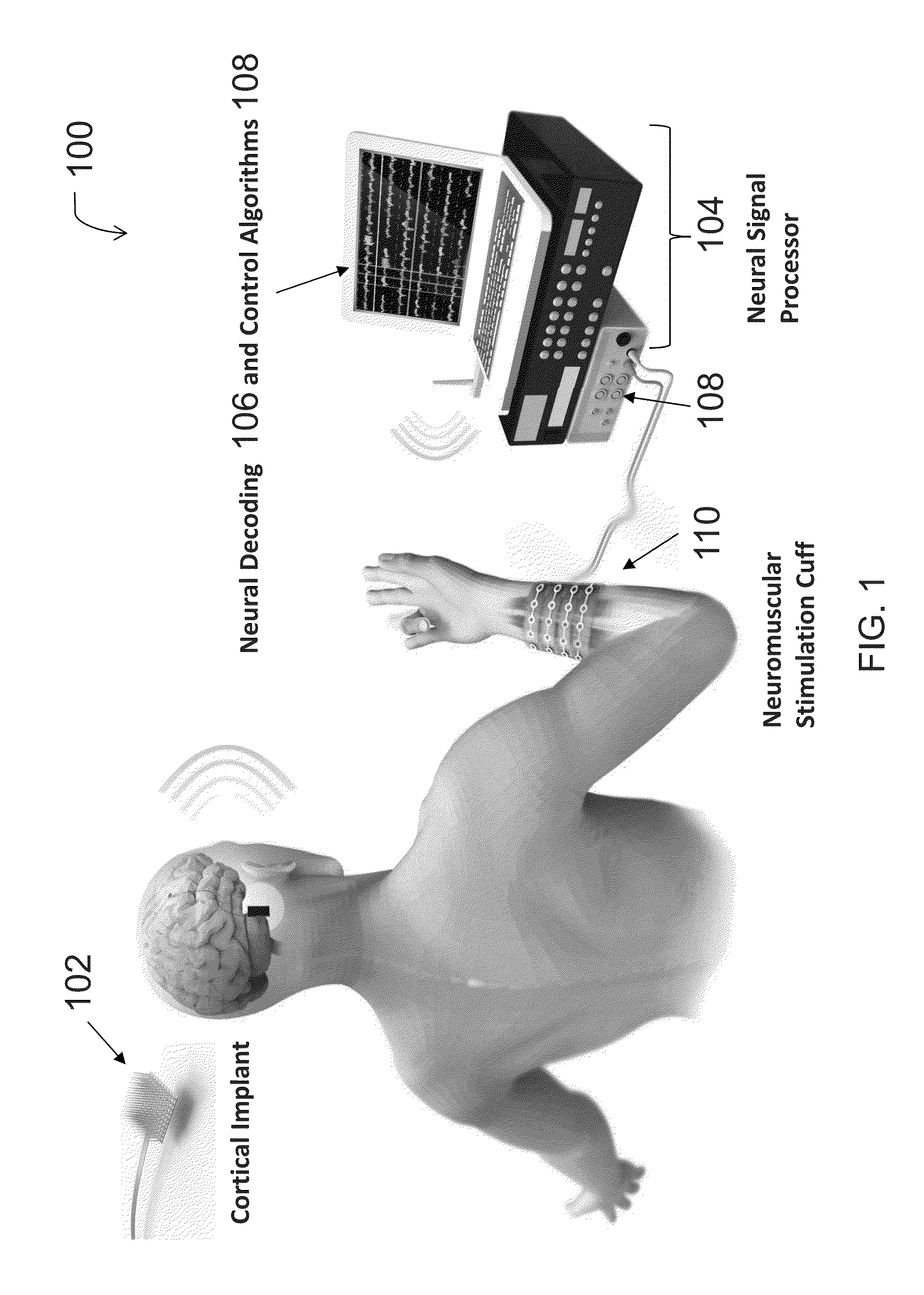
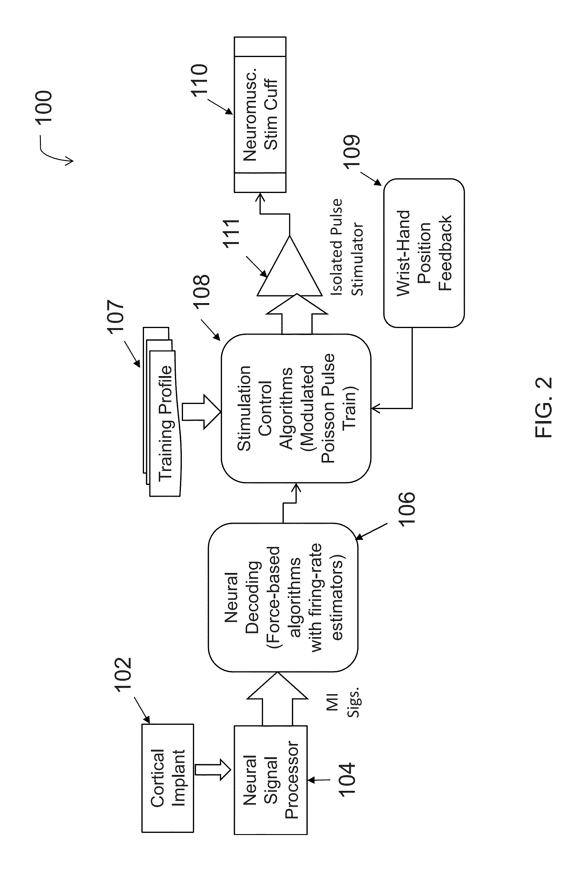
[0056]With reference to FIG. 1 and FIG. 2, a system for thought-controlled neuromuscular stimulation may include a cortical implant 102 implanted into the cerebral cortex region of the brain. The cortical implant 102 in one embodiment includes a microelectrode sensing array...


PUM


Abstract

The present disclosure relates to neuromuscular stimulation and sensing cuffs. The neuromuscular stimulation cuff has at least two fingers and a plurality of electrodes disposed on each finger. More generally, the neuromuscular stimulation cuff includes an outer, reusable component and an inner, disposable component. One or more electrodes are housed within the reusable component. The neuromuscular stimulation cuff may be produced by providing an insulating substrate layer, forming a conductive circuit on the substrate layer to form a conductive circuit layer, adhering a cover layer onto the conductive circuit layer to form a flexible circuit, and cutting at least one flexible finger from the flexible circuit. The neuromuscular stimulation cuff employs a flexible multi-electrode design which allows for reanimation of complex muscle movements in a patient, including individual finger movement.

Description

CROSS-REFERENCE TO RELATED APPLICATIONS[0001]This application is a continuation-in-part of U.S. patent application Ser. No. 14 / 649,025, filed on Jun. 2, 2015, which is a 371 of PCT Application No. PCT / US2013 / 073247, filed on Dec. 5, 2013, which claimed priority to both U.S. Provisional Patent Application Ser. No. 61 / 733,736, filed on Dec. 5, 2012, and to U.S. Provisional Patent Application Ser. No. 61 / 734,150, filed on Dec. 6, 2012.BACKGROUND[0002]The following relates generally to systems, methods and devices for neuromuscular stimulation, sensing, and recording. Generally, the system may be used to receive thought signals indicative of an intended action and provide electrical stimulation to nerves and / or muscles to effectuate the intended action, thereby bypassing or assisting a damaged or degenerated region / pathway of the nervous system. The devices of the present disclosure are neuromuscular stimulation cuffs, also referred to herein as “neural sleeves,” which deliver stimulati...

Claims


Application Information

Patent Timeline
Patent Type & Authority Applications(United States)
IPC IPC(8): A61N1/04G06F3/01A61N1/36
CPCA61N1/0484G06F3/017A61N1/36003A61N1/0456G06F3/015
Inventor BOUTON, CHAD E.FRIEND, JEFFREYSHARMA, GAURAVSWEENEY, ANDREWHEINTZ, AMY M.KUTE, STEPHANIEANNETTA, NICHOLASHAUBERT, THOMAS D.RISSER, STEVEN M.
Owner BATTELLE MEMORIAL INST
Why Eureka
Try Eureka