Airborne wind energy system for electricity generation, energy storage, and other uses

a technology of airborne wind energy and electricity generation, which is applied in the direction of wind energy generation, liquid fuel engine components, non-positive displacement fluid engines, etc., can solve the problems of not teaching the efficiency conversion of wind power into other forms of energy, unable to teach the efficiency conversion of wind power into anything other than vehicle propulsion and electricity generation, etc., to achieve the effect of improving the efficiency of natural gas power plants

Inactive Publication Date: 2015-10-29
GOLDSTEIN LEONID
View PDF3 Cites 19 Cited by
  • Summary
  • Abstract
  • Description
  • Claims
  • Application Information

AI Technical Summary

Benefits of technology

[0020]Another embodiment of the invention is a method of improving efficiency of a natural gas power plant, in which some of the mechanical energy for air compression prior to combustion is supplied by an airborne wind energy conversion system.

Problems solved by technology

It mentions possibility of using a hydraulic cylinder and a hydraulic motor for converting mechanical energy delivered by the tether into electricity, but does not disclose how to do that.
None of the references above teach efficient conversion of wind power into anything else but vehicle propulsion and electricity generation.
More specifically, they do not teach conversion of wind energy into other forms of energy than electricity, storing harvested wind energy in energy storage, providing wind power stations with a firm capacity, independent of the wind.
They do not teach conversion of wind power, harvested by airborne wings or kites, into electricity through pneumatic or hydraulic action.
They do not teach conversion of wind power into heat, compressed air or other forms, suitable for powering industrial processes.

Method used


Image

  • Airborne wind energy system for electricity generation, energy storage, and other uses
  • Airborne wind energy system for electricity generation, energy storage, and other uses
  • Airborne wind energy system for electricity generation, energy storage, and other uses

Examples


Embodiment Construction

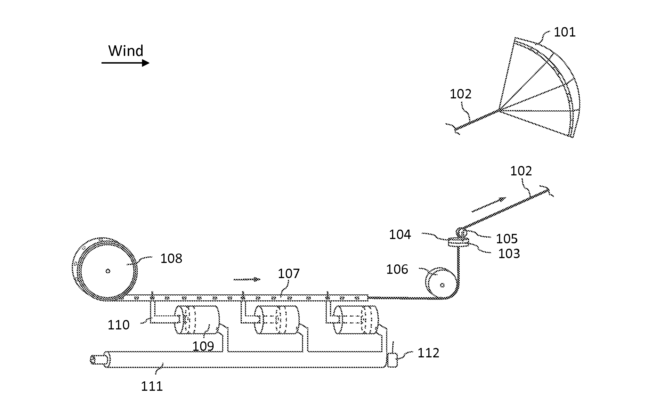
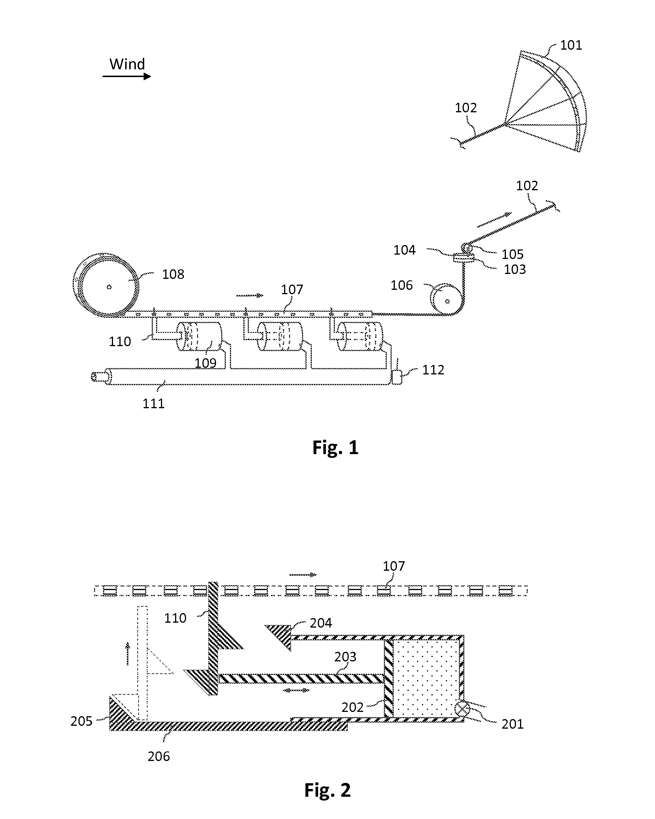
[0072]FIG. 1 shows one embodiment of the invention. It comprises an airborne wing 101, harvesting wind energy by moving cross wind. A tether 102 is attached to wing 101. Other elements of the construction, shown in FIG. 1 and described below, are installed on the ground. Particulars of attachment of the elements to the walls, ground and other supporting structures are not shown to avoid clutter. There is a ring 103, installed on a slightly elevated structure. Another ring 104 is installed on top of ring 103 on ball bearings and is capable of horizontal rotation to accommodate changes in the direction of the wind. A vertical pulley 105 is installed on ring 104. Tether 102 wraps around pulley 104 and drops inside of rings 103 and 104, so that it remains vertical no matter how ring 104 with pulley 105 rotate. Tether 102 goes around a vertical pulley 106, as shown in FIG. 1, so that it comes out horizontally. A perforated belt (or a chain) 107 is attached at the end of tether 102 and wi...


PUM


Abstract

Airborne wind energy system converting power of wind into power forms suitable for various industrial processes. That includes converting wind energy into internal energy of hot compressed gas, such as air or steam, and subsequent use of this energy for energy storage, synthetic fuel production, electricity generation, and other purposes. Pumped hydro energy storage, powered by airborne wind energy. A combined power plant, using natural gas combustion and wind power. A wind farm with a firm capacity, using wind driven energy storage together with electricity producing wind turbines or AWECS.

Description

CROSS REFERENCE TO RELATED APPLICATIONS[0001]This application is a continuation of PCT Application No. PCT / US13 / 73766, filed 8 Dec. 2013, which claims the benefit of U.S. Provisional Applications No. 61 / 746,238, filed 27 Dec. 2012, No. 61 / 747,446, filed 31 Dec. 2012, No. 61 / 760,150, filed 3 Feb. 2013, No. 61 / 762,257, filed 7 Feb. 2013, No. 61 / 771,197, filed 1 Mar. 2013, and No. 61 / 872,956, filed 3 Sep. 2013 by the same inventor as herein, the entire disclosure of which is incorporated herein by reference.BACKGROUND OF THE INVENTION[0002]The invention is generally directed to a device and a method for using wind power, utilizing an airborne wind energy harvesting member.[0003]The classical work in the airborne wind energy conversion systems (AWECS) is the article by Miles L. Loyd “Crosswind Kite Power” (Energy Journal, 1980; 4:106-11), in which the author disclosed a wind energy harvesting device, comprising a tethered wing, flying cross wind and harvesting wind energy, and transferr...

Claims


Application Information

Patent Timeline
Patent Type & Authority Applications(United States)
IPC IPC(8): F03D9/00F03D5/02F01D13/02F03D11/04
CPCF03D9/002F03D11/04F05D2220/32F01D13/02F05B2240/92F03D5/02F03D5/00F03D5/06F03D9/10F03D9/17F03D9/18F03D9/25F03D13/20Y02E10/70Y02E10/72Y02E10/728Y02E60/16Y02E70/30Y02P80/20
Inventor GOLDSTEIN, LEONID
Owner GOLDSTEIN LEONID
Why Eureka
Try Eureka