Apparatus and Method for Sample Preparation

a sample and apparatus technology, applied in the field of apparatus and sample preparation, can solve the problems of unevenness or soft parts being crushed, difficult to prepare a sample section without varying the morphology or composition of the sample, and difficult to smoothly polish a joint or interface between materials having different degrees of hardness, etc., to achieve the effect of efficiently preparing thin amorphous regions

Inactive Publication Date: 2015-10-29
JEOL LTD
View PDF1 Cites 2 Cited by
  • Summary
  • Abstract
  • Description
  • Claims
  • Application Information

AI Technical Summary

Benefits of technology

[0009]In this sample preparation apparatus, a cross section having a thin amorphous region can be prepared efficiently.
[0013]In this sample preparation method, a cross section having a thin amorphous region can be prepared efficiently.
[0015]In this sample preparation method, a cross section having a thin amorphous region can be prepared efficiently.
[0017]In this sample preparation method, a cross section having a thin amorphous region can be prepared efficiently.

Problems solved by technology

In mechanical polishing, however, a force is applied to the surface to be processed and so softer portions may be erased earlier, resulting in unevenness or softer portions may be crushed.
Furthermore, in some cases, a harder material is buried in a softer portion.
Therefore, when a method of mechanical polishing is employed, it has been difficult to smoothly polish a joint or interface between materials having different degrees of hardness.
In this way, with a method of mechanical polishing, it has been difficult to prepare a sample section without varying the morphology or composition of the sample.
However, it is known that even if a sample preparation apparatus such as the sample preparation apparatus of JP-A-2011-192521 that uses an ion beam and an ion beam shielding material is employed, when a crystalline sample section is prepared, the crystallinity of the topmost surface is disturbed.

Method used


Image

  • Apparatus and Method for Sample Preparation
  • Apparatus and Method for Sample Preparation
  • Apparatus and Method for Sample Preparation

Examples


first embodiment

1. First Embodiment

1.1. Sample Preparation Apparatus

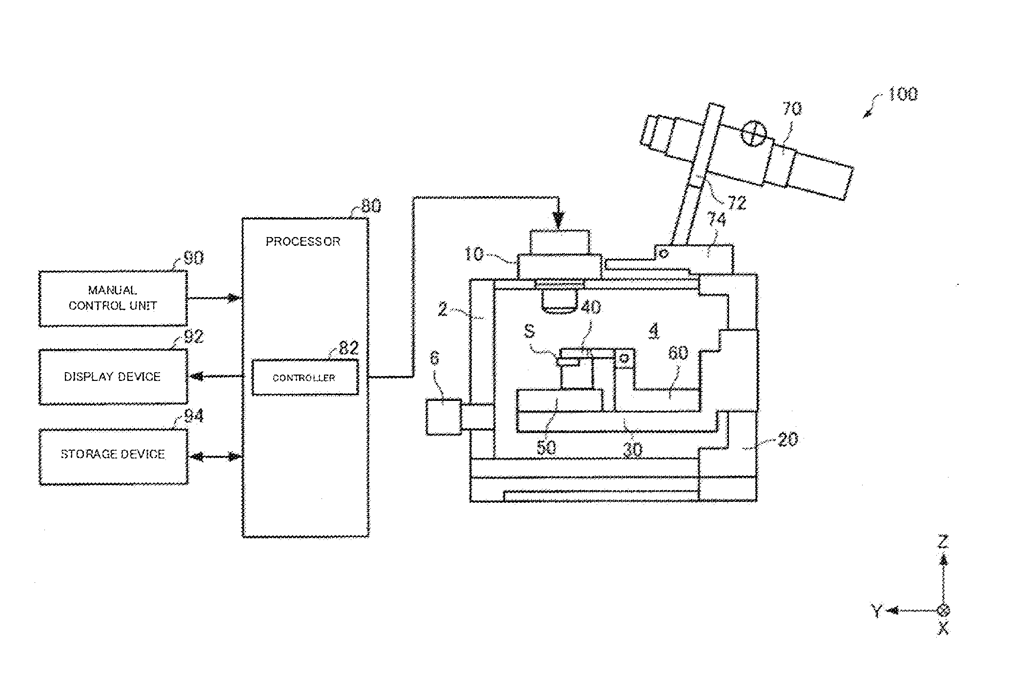
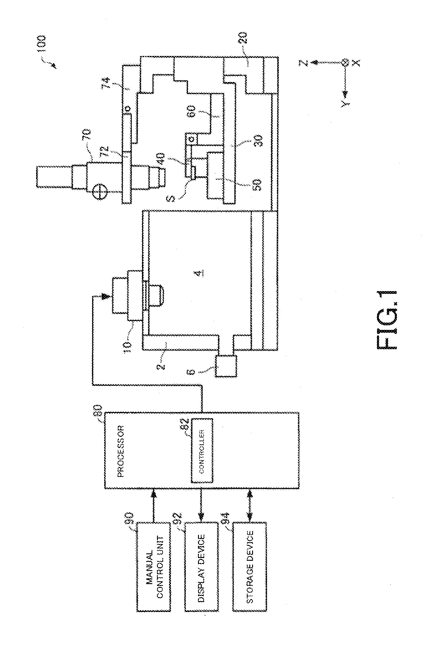
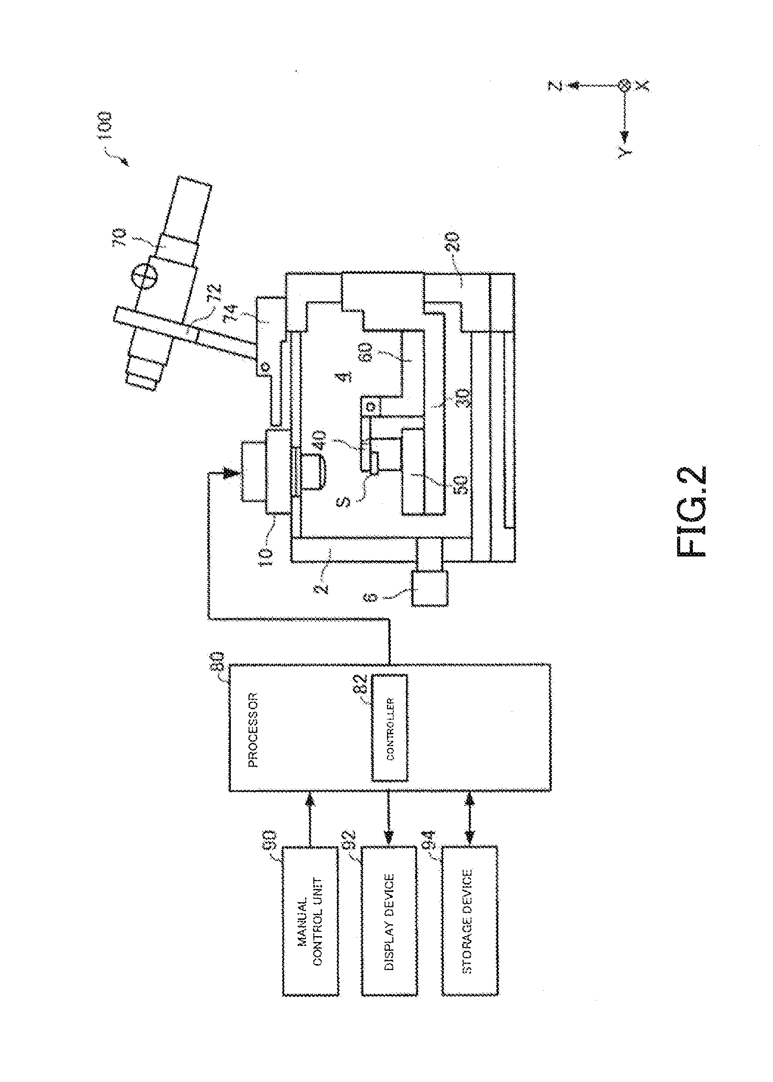
[0028]A sample preparation apparatus associated with a first embodiment of the present invention is first described by referring to FIGS. 1 and 2, which schematically show the sample preparation apparatus, generally indicated by reference numeral 100. In FIGS. 1 and 2, for the sake of convenience, X-, Y-, and Z-axes are shown as three axes perpendicular to each other.

[0029]As shown in FIG. 1, the sample preparation apparatus 100 includes an ion beam generator 10, a sample stage extracting mechanism 20, a sample stage 30, a shield plate 40, a sample position adjusting mechanism 50, a shield plate position adjusting mechanism 60, an optical microscope 70, a processor 80, a manual control unit 90, a display device 92, and a storage device 94. FIG. 1 shows a state in which the sample stage extracting mechanism 20 is open. FIG. 2 shows a state in which the extracting mechanism 20 is closed.

[0030]The ion beam generator 10 produces an ion...

second embodiment

2. Second Embodiment

[0061]A sample preparation apparatus associated with a second embodiment of the present invention is next described. This apparatus is similar in configuration to the above-described sample preparation apparatus 100 associated with the first embodiment and already described in connection with FIGS. 1-3. In the following, only the differences with the sample preparation apparatus 100 associated with the first embodiment are described.

[0062]FIG. 8 shows one example of control GUI screen of the sample preparation apparatus associated with the second embodiment. As shown in FIG. 8, the control GUI screen of the sample preparation apparatus associated with the second embodiment does not have the finish processing check column 924 unlike the control GUI screen of the sample preparation apparatus 100 shown in FIG. 6.

[0063]In the sample preparation apparatus associated with the second embodiment, if the processing start button 922 is depressed, a coarse processing operat...


PUM


Abstract

A sample preparation apparatus (100) is used to prepare a cross section of a sample (S) by irradiating it with an ion beam. The apparatus (100) includes an ion beam generator (10), a shield plate (40) disposed to cover a part of the sample (S) to shield the sample (S) from the ion beam, and a controller (82) controlling the ion beam generator (10). The controller (82) controls performance of first and second operations. In the first operation, the ion beam is accelerated by a first accelerating voltage and hits the sample (S) while the sample (S) and the shield plate (40) are located in a given positional relationship. In the second operation, the ion beam is accelerated by a second accelerating voltage lower than the first accelerating voltage and hits the sample (S) while the given positional relationship is maintained.

Description

BACKGROUND OF THE INVENTION[0001]1. Field of the Invention[0002]The present invention relates to an apparatus and method for sample preparation.[0003]2. Description of Related Art[0004]Mechanical polishing of a sample is known as a method of preparing a sample to be observed or analyzed by an electron microscope. In mechanical polishing, however, a force is applied to the surface to be processed and so softer portions may be erased earlier, resulting in unevenness or softer portions may be crushed. Furthermore, in some cases, a harder material is buried in a softer portion. Therefore, when a method of mechanical polishing is employed, it has been difficult to smoothly polish a joint or interface between materials having different degrees of hardness. In this way, with a method of mechanical polishing, it has been difficult to prepare a sample section without varying the morphology or composition of the sample.[0005]Faced with this problem, JP-A-2011-192521 discloses a sample prepara...

Claims


Application Information

Patent Timeline
Patent Type & Authority Applications(United States)
IPC IPC(8): H01J37/09H01J37/22H01J37/08
CPCH01J37/09H01J37/226H01J37/08G01N1/32
Inventor NEGISHI, TSUTOMU
Owner JEOL LTD
Why Eureka
Try Eureka