Polarization Control in High Peak Power, High Brightness VCSEL

Inactive Publication Date: 2015-10-29
PRINCETON OPTRONICS
View PDF7 Cites 57 Cited by
  • Summary
  • Abstract
  • Description
  • Claims
  • Application Information

AI Technical Summary

Benefits of technology

[0024]According to one aspect of the invention monolithically integrated high power, high brightness VCSEL and VCSEL arrays (VCSEL devices) are provided according to high volume manufacturing processes. In particular, VCSEL devices comprising monolithically integrated multilayer top and bottom DBRs (top and bottom mirrors/reflectors)

Problems solved by technology

However, in earlier devices, producing VCSELs and OEICs using VCSELs in large volume compatible with high volume production processes was a challenge because of several limitations pertaining to large area defect free wafer growth, defect and stress free growth of epitaxial layers that form the foundation structure of the VCSEL devices, and absence of compatible wafer processing methods to include different semiconductor material on a common compatible platform.
While the three mirror VCSEL designs mentioned earlier are relatively successful in achieving high output power, the output power and brightness (defined as high output power in a single mode) is limited by total volume of a single gain region or light emitting region in the gain cavity of a typical VCSEL device.
Those skilled in the art may be able to appreciate that an n-layer in close contact with a p-layer of adjacent gain region in the VCSEL cavity may result in restrictive carrier flow in the gain

Method used


Image

  • Polarization Control in High Peak Power, High Brightness VCSEL
  • Polarization Control in High Peak Power, High Brightness VCSEL
  • Polarization Control in High Peak Power, High Brightness VCSEL

Examples


Embodiment Construction

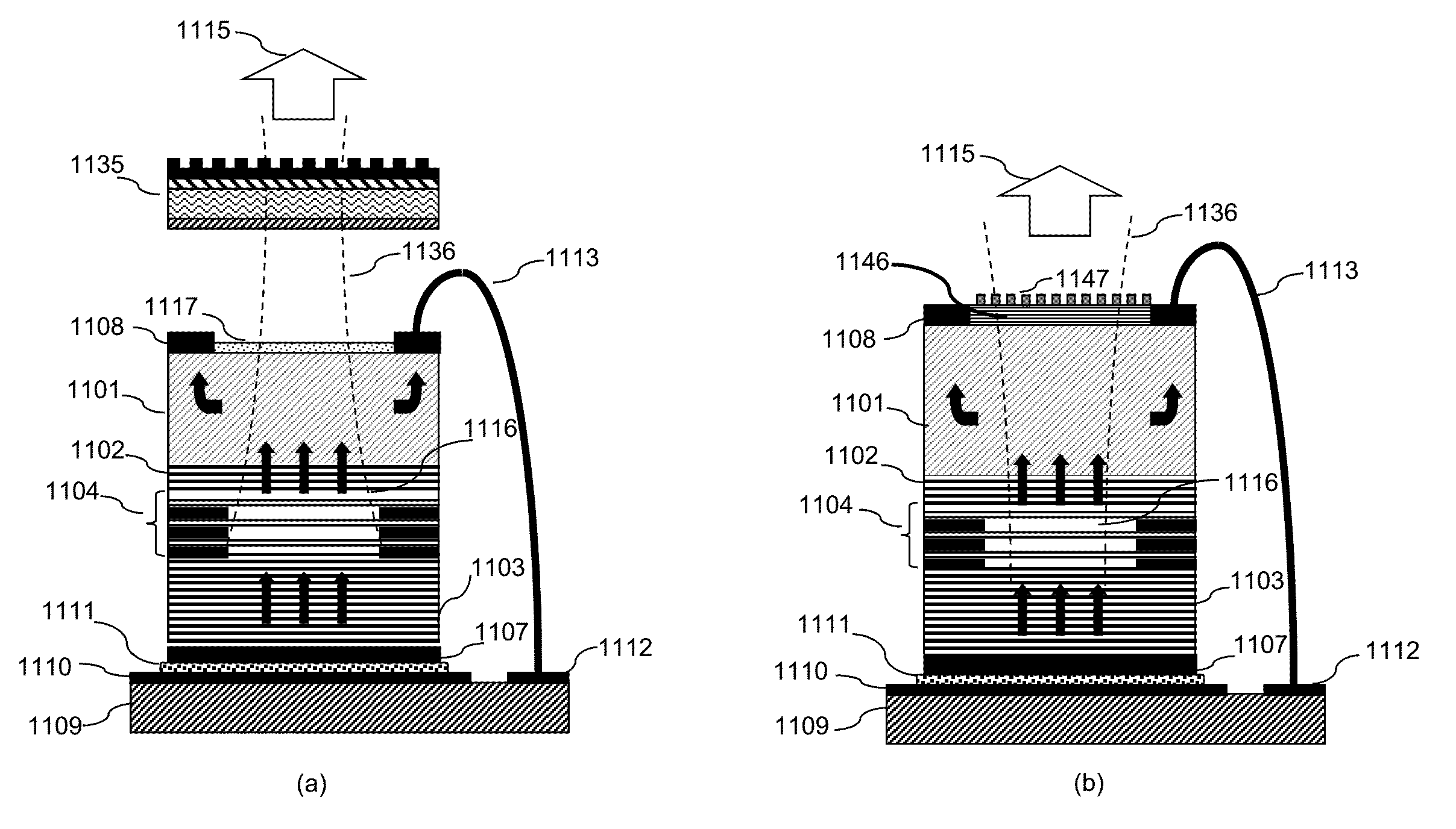
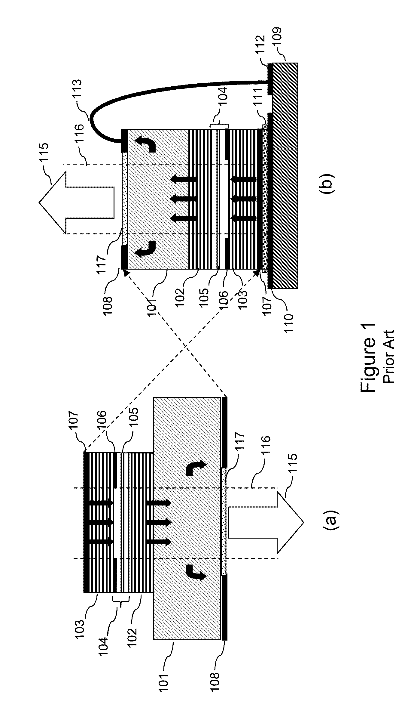
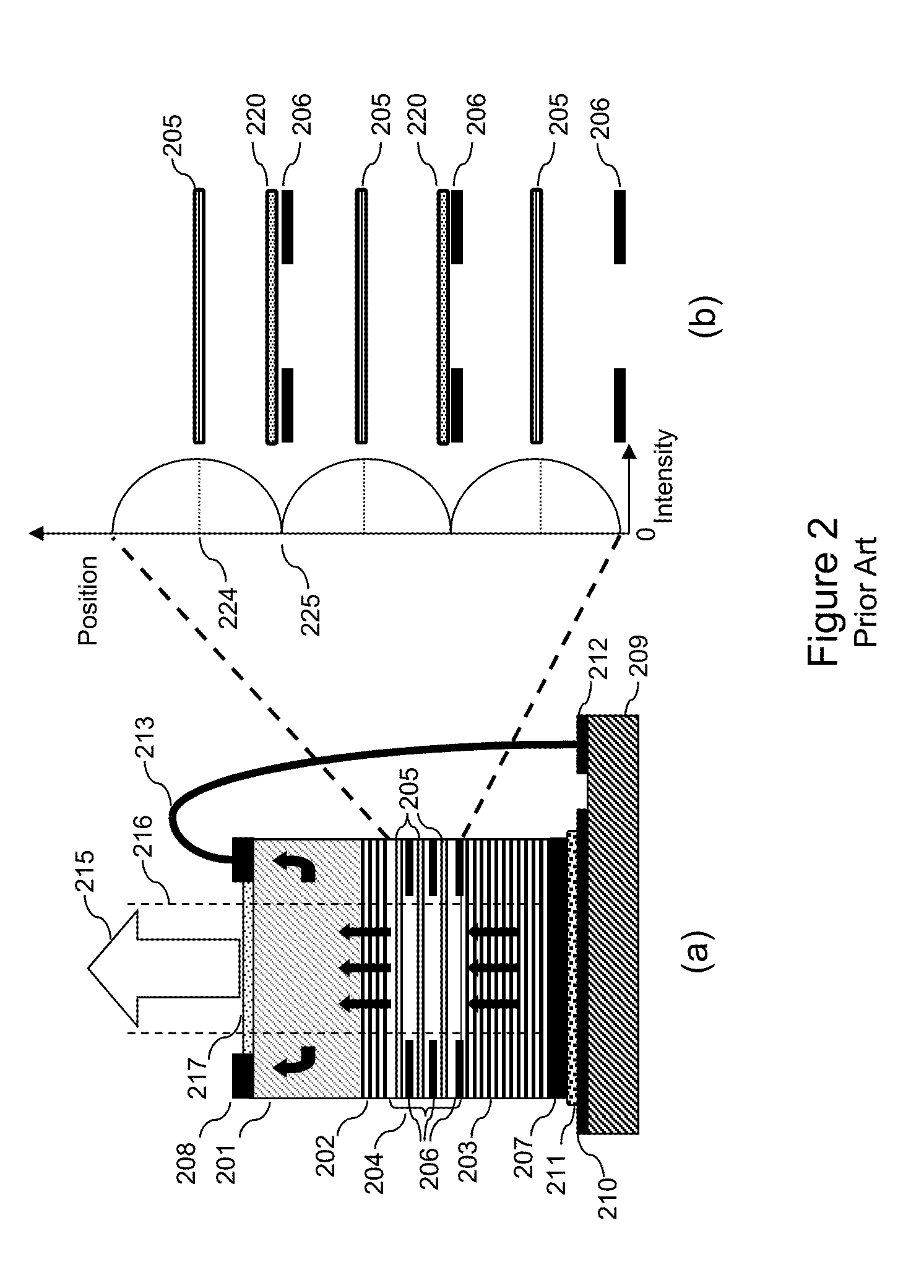
[0049]A broad framework of the principles will be presented by describing various aspects of this invention using exemplary embodiments represented in different drawing figures. For clarity and ease of description, each embodiment includes only a few aspects at a time. However, it should be understood that different aspects of different embodiments may be combined or practiced separately, in for best mode practice. To keep the description short, drawing figures are labelled to identify similar elements or elements having equivalent functions with similar reference numeral in which the first number always refers to the figure number (e.g., 101, 201, 301, etc. will refer to a substrate in all the drawing figures). Many different combinations and sub-combinations of the representative embodiments to be described within the broad framework of this invention, that may be apparent to those skilled in the art but not explicitly shown or described, should not be construed as precluded.

High ...


PUM


Abstract

A new VCSEL design is presented to achieve high output power and high brightness with a strong selection of a linear polarization state in high speed pulsing operation. Higher output power is achieved by including multiple gain segments in tandem, in the gain region. To achieve single mode operation with high output power, an extended cavity three reflector design is presented. High degree of polarization selectivity is achieved by a linear grating deployed with the third reflector, such that lasing is allowed only in a preferred linear polarization state. A polarization selective reflector including a linear grating is designed to impart strong polarization selectivity for a preferred linear polarization state. The polarization selective reflector used as the third reflector in an extended cavity VCSEL device, exhibits strong polarization selection for a preferred linear polarization state during high speed pulsing including in the gain switching resonance regime.

Description

CROSS REFERENCE TO RELATED APPLICATION[0001]The present application seeks priority from the United States Provisional Patent Application No. 61 / 985,776 filed on Apr. 29, 2014, the content of which is being incorporated by reference in its entirety.BACKGROUND OF THE INVENTION[0002]1. Field of the Invention[0003]The present invention relates to high brightness VCSELs including single VCSEL and VCSEL arrays, and in particular to extended cavity VCSELs having high peak power and high brightness emission with linear polarization, suitable for high speed pulse operation.[0004]2. Related Background Art[0005]VCSELs have many beneficial properties over other lasers, especially edge emitting semiconductor lasers. They can generate round beams of radiation with good collimation for many different wavelengths. They are stable with varying operating temperature having very small changes in operating wavelength contributing significantly to long-term reliability. VCSELs are operable using very sh...

Claims


Application Information

Patent Timeline
IPC IPC(8): H01S5/068H01S5/02H01S5/183H01S5/42H01S5/187H01S5/042
CPCH01S5/06821H01S5/187H01S5/0425H01S5/18355H01S5/423H01S5/0217H01S5/1838H01S5/18361H01L2224/16225H01L2224/48091H01L2224/73265H01S3/08068H01S5/0422H01S5/141H01S5/18305H01S5/1833H01S5/18383H01S5/18386H01S5/02325H01S5/0234H01L2924/00014
Inventor WANG, QINGSEURIN, JEAN-FRANCOISGHOSH, CHUNI LWATKINS, LAURENCE S
Owner PRINCETON OPTRONICS
Why Eureka
Try Eureka