Current limiting device, current limiter and current limiting system for power grid

a technology of current limiter and power grid, applied in the electrical field, can solve the problems of increased length of connecting bus bars, increased risk, and inability to install or use conveniently, and achieve the effect of improving the operational reliability of the power grid

Inactive Publication Date: 2015-11-05
STATE GRID NINGXIA ELECTRIC POWER TECHN RES INST +2
View PDF7 Cites 13 Cited by
  • Summary
  • Abstract
  • Description
  • Claims
  • Application Information

AI Technical Summary

Benefits of technology

[0024]In the disclosure, a first current limiting reactor is connected into a circuit in a serial connection manner by switching off a first smart fast switch to limit a current and short-circuited by switching on the first smart fast switch when a fault is elim

Problems solved by technology

Limited by an insulation level, most high-capacity fast switches are used in a 6-35 kV high voltage chamber, and the high-capacity fast switches having many operational links, which are limited by many conditions, cannot be installed or used conveniently and are increased in the length of connecting bus bars, are more likely to malfunction and have more risks.
The short-circuit current of a pow

Method used


Image

  • Current limiting device, current limiter and current limiting system for power grid
  • Current limiting device, current limiter and current limiting system for power grid
  • Current limiting device, current limiter and current limiting system for power grid

Examples


Embodiment Construction

[0036]It should be noted that embodiments of the disclosure and the features thereof can be combined with each other if no conflict is caused. The disclosure is described below in detail with reference to accompanying drawings when read in conjunction with embodiments.

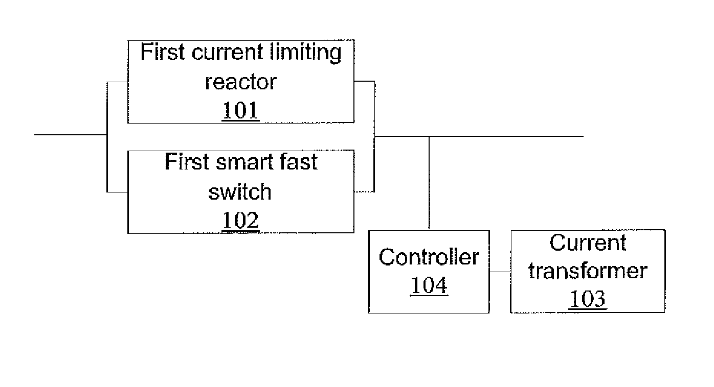
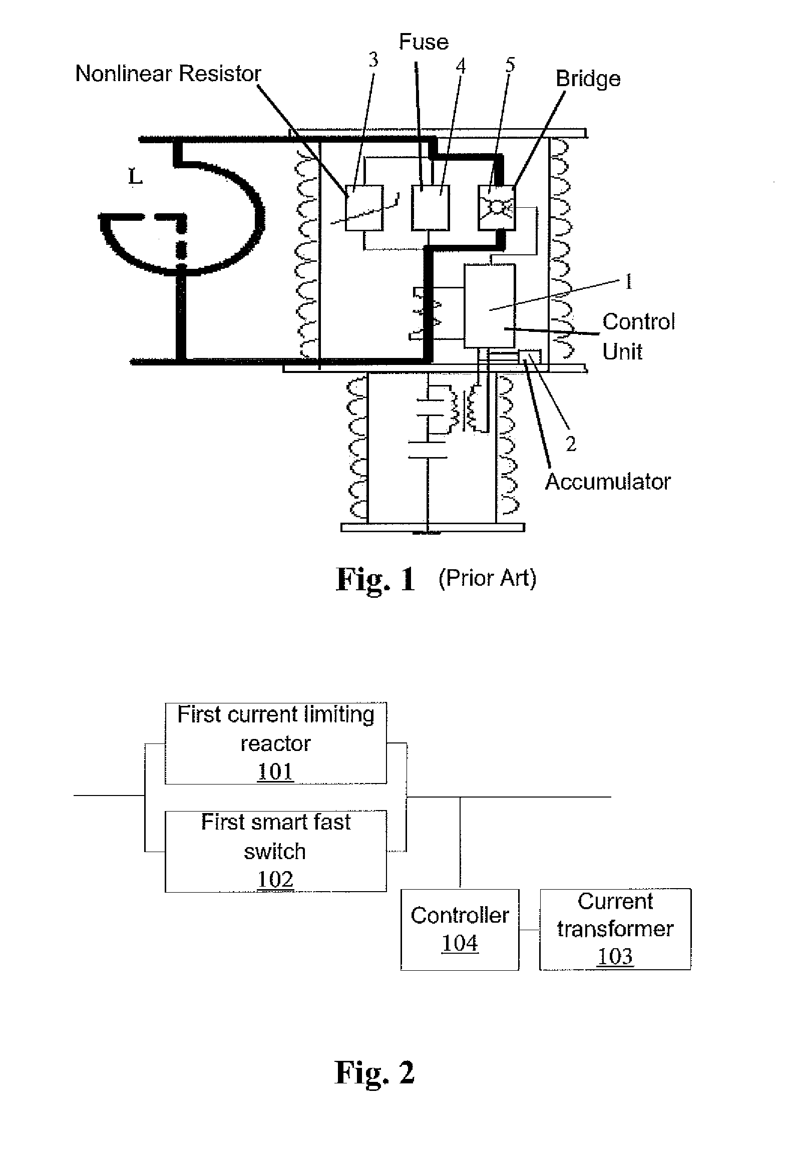
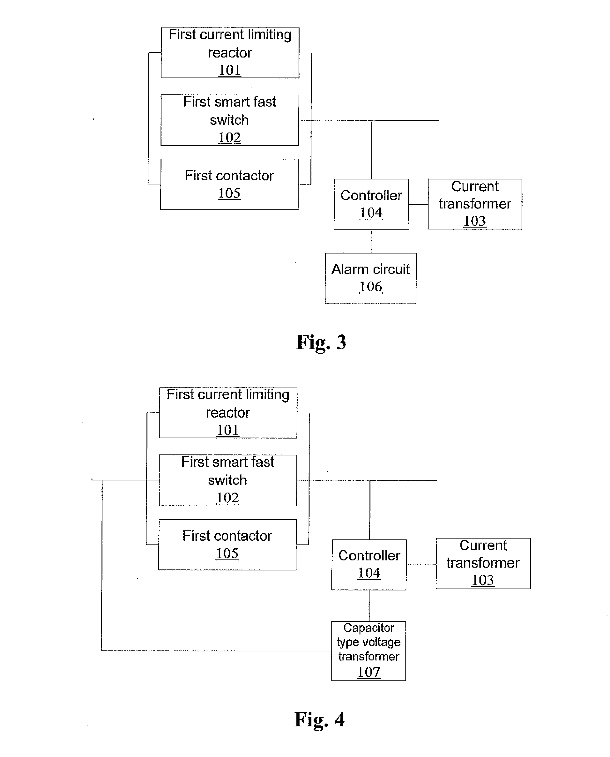
[0037]FIG. 2 is a diagram illustrating the structure of a current limiting device for a power grid according to an embodiment of the disclosure, and as shown in FIG. 2, the current limiting device for a power grid provided in the embodiment includes:[0038]a first current limiting reactor 101,[0039]preferably, the first current limiting reactor is a hollow current limiting reactor;[0040]a first smart fast switch 102 connected with the first current limiting reactor 101 in parallel;[0041]a current transformer 103 sleeved on a bus bar located on one side of a circuit resulting from the parallel connection of the first current limiting reactor 101 with the first smart fast switch 102 so as to monitor the current in the bus...


PUM


Abstract

A current limiting device for a power grid includes a first current limiting reactor; a first smart fast switch connected with the first current limiting reactor in parallel; a current transformer sleeved on a bus bar located on one side of a circuit resulting from the parallel connection of the first current limiting reactor with the first smart fast switch to monitor the current in the bus bar in real time; and a controller connected with the current transformer to control the switch-off of the first smart fast switch when the current in the bus bar is higher than a first preset value and the switch-on of the first smart fast switch when the current in the bus bar is smaller than a second preset value, wherein the first preset value is higher than the second preset value. The current limiting device improves the operational reliability of a power grid.

Description

FIELD OF THE INVENTION[0001]The disclosure relates to the electrical field and more particularly to a current limiting device, a current limiter and a current limiting system for a power grid.BACKGROUND OF THE INVENTION[0002]With the development of power grids, the maximum short-circuit currents of the power grids in many regions have exceeded the interrupting capacity (63 kA at most, currently) of a breaker. For the sake of this limitation, a more effective short-circuit current breaking technology is desired.[0003]A high-capacity fast switch has been domestically developed early which adopts the combination of an exploding fast breaking current-carrying bridge with a high-voltage current limiting fuse and a zinc oxide resistor having a high energy absorption capacity and which can be switched on / off at the beginning of the rise of a short-circuit current to limit the rise of the short-circuit current and cut off the short-circuit current within 1 ms when the short-circuit current ...

Claims


Application Information

Patent Timeline
IPC IPC(8): H02H9/02
CPCH02H9/02H02H9/021
Inventor AI, SHAOGUIWANG, CHUANHUANG, YONGNINGFAN, YIPINGZHANG, GUOYONGLI, YANJUNPAN, NINGZHANG, SHUANG
Owner STATE GRID NINGXIA ELECTRIC POWER TECHN RES INST
Why Eureka
Try Eureka