
Pre-Distortion of an Optical Signal with Frequency Division Multiplexed Sub-Carriers

a frequency division multiplexing and optical signal technology, applied in the field of transmission of optical signals, can solve the problems of large degraded performance in reception of such an optical signal, inability to guarantee the perfect rectangular nature of the narrow spectral transfer function of the optical filter, in particular of the sub-band multiplexer, and inability to achieve the effect of limiting the impact on a multi-carrier signal

Active Publication Date: 2015-11-05
ORANGE SA (FR)
View PDF4 Cites 4 Cited by
  • Summary
  • Abstract
  • Description
  • Claims
  • Application Information

AI Technical Summary

Benefits of technology

The patent describes a method for improving the quality of optical signals transmitted through optical lines. By using corrective factors in the electrical domain, the method can neutralize deformations in the spectrum of the optical signal during transmission. This helps to limit the impact of optical components, such as multiplexers, on the optical signal. The method also includes a preliminary configuration step to measure the values of certain parameters and calculate the corrective factors based on those measurements. These corrective factors can then be stored for future reference. Overall, the method helps to ensure the reliable and accurate transmission of optical signals.

Problems solved by technology

Now, the perfectly rectangular nature of the narrow spectral transfer function of the optical filters, in particular of the sub-band multiplexers, cannot be guaranteed.
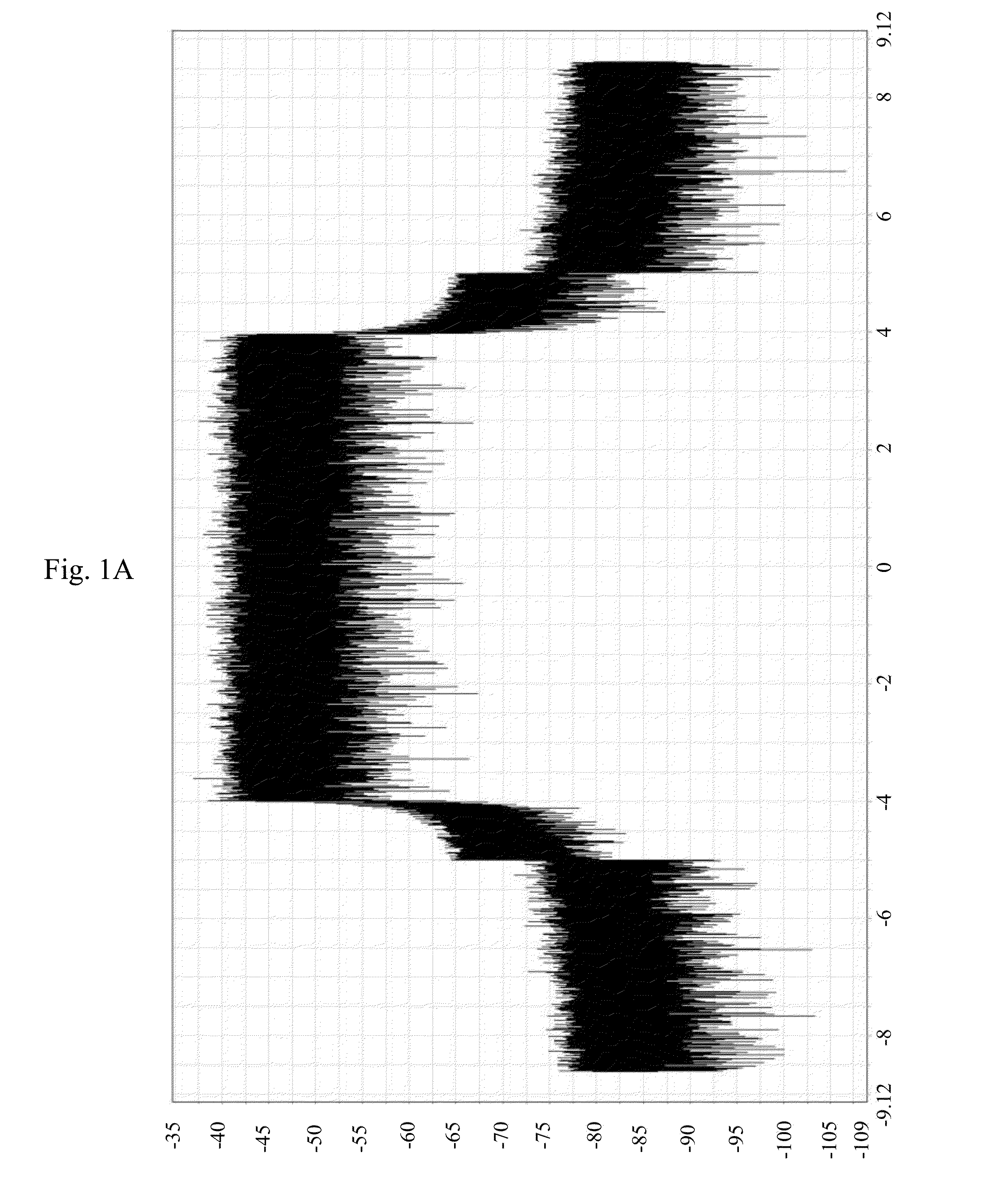
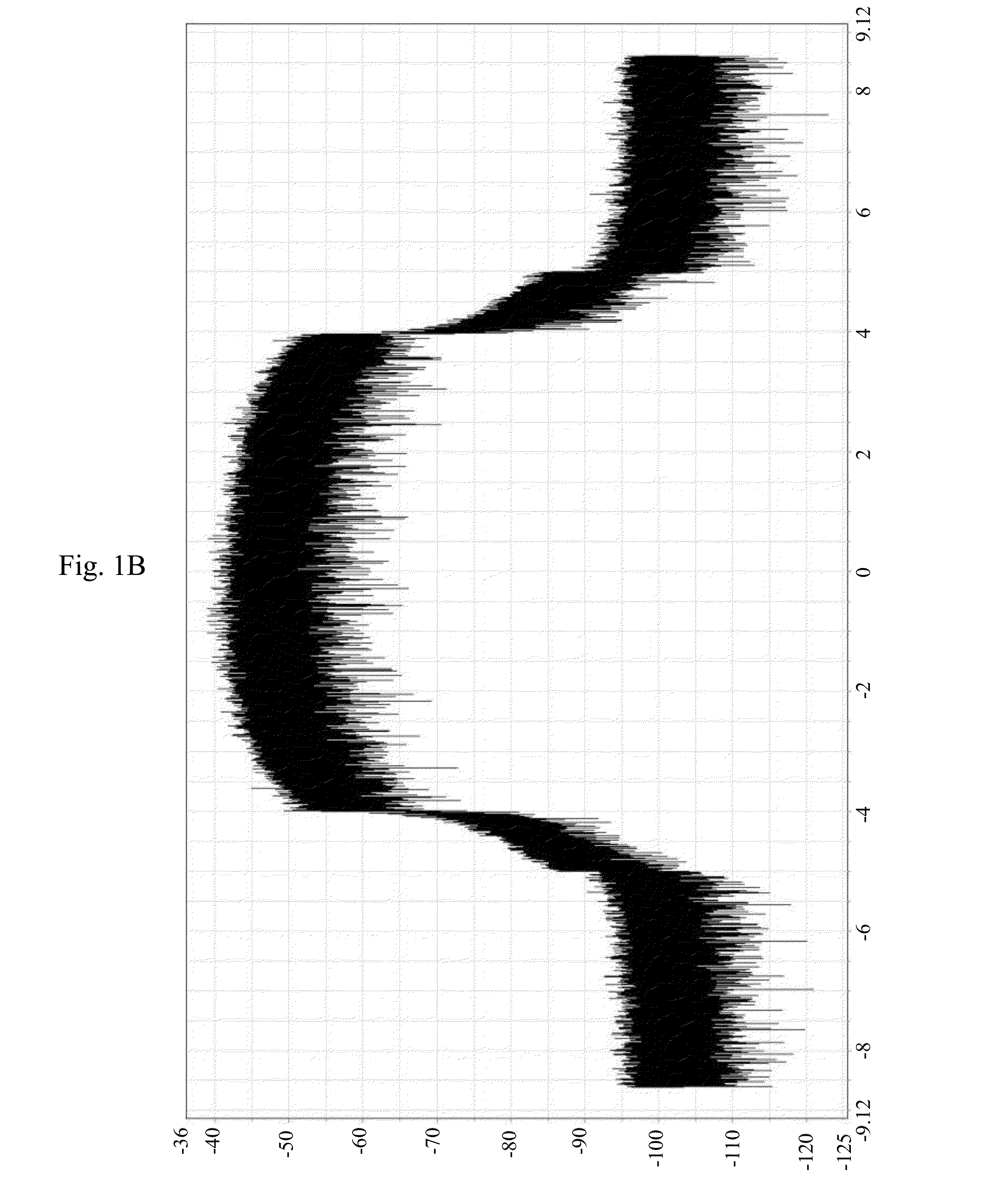
The performance in reception of such an OFDM optical signal is greatly degraded, in that the different constituent sub-bands of this OFDM signal then exhibit extremely variable bit error ratios (BER), the signal-to-noise ratio (SNR) between these different sub-carriers no longer being at all the same at the receiver of this OFDM signal.

Method used


Image

  • Pre-Distortion of an Optical Signal with Frequency Division Multiplexed Sub-Carriers
  • Pre-Distortion of an Optical Signal with Frequency Division Multiplexed Sub-Carriers
  • Pre-Distortion of an Optical Signal with Frequency Division Multiplexed Sub-Carriers

Examples


Embodiment Construction

[0035]Reference is first of all made to FIG. 2 which illustrates an optical transmission system in which an aspect of the present disclosure can be implemented.

[0036]This transmission system comprises optical transmitters (a single transmitter 10 being illustrated here, in a nonlimiting manner) connected, via an optical wavelength division multiplexer 20, to the input of an optical transmission line 30. The output of this optical transmission line 30 is connected to a plurality of optical receivers (just one receiver 50 being illustrated here, in a nonlimiting manner), via an optical wavelength division demultiplexer 40.

[0037]In such a system, each optical transmitter transmits an optical sub-band comprising N frequency division multiplexed sub-carriers (N being equal to 2k, k being an integer, for example N=128, 256, 512, . . . ), and the different optical sub-bands are wavelength division multiplexed in order to construct an optical signal of “super-channel” type and are thus tran...


PUM


Abstract

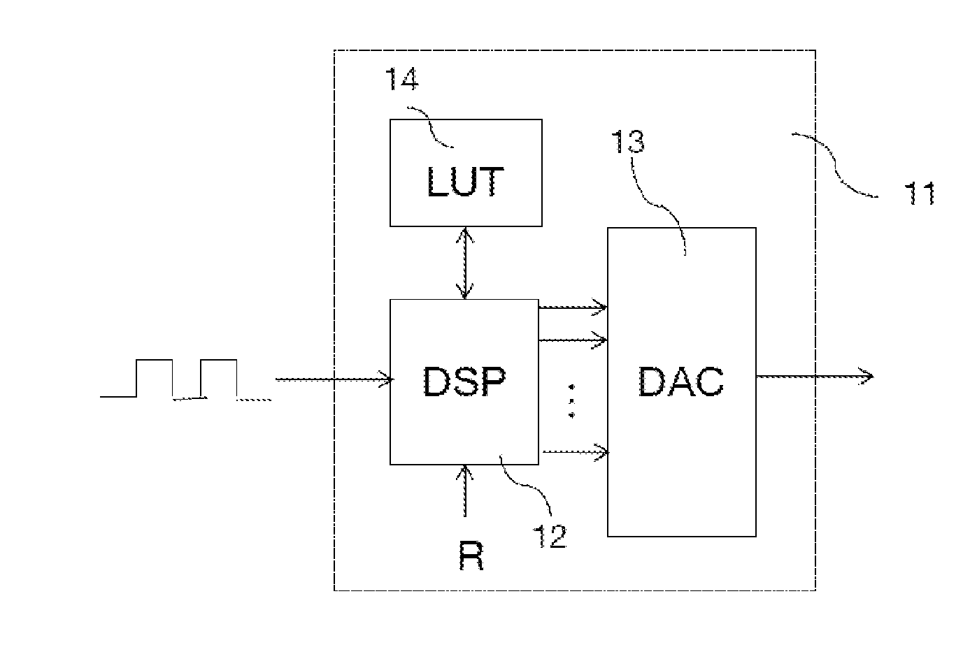
A method is provided for pre-distorting an optical signal, intended to be transmitted over an optical transmission line and including a plurality of frequency division multiplexed optical sub-carriers. The optical signal is obtained from an optical conversion of an electrical signal including a plurality of frequency division multiplexed sub-carriers. This method includes obtaining a plurality of corrective factors, corresponding to the electrical sub-carriers, as a function of a plurality of values, determined for the optical sub-carriers, of a first parameter dependent on the power of the sub-carriers, and application of the corrective factors to the amplitudes of the corresponding electrical sub-carriers, so as to equalize, at the output of the optical transmission line, the values of the first parameter for the sub-carriers of the optical signal.

Description

CROSS-REFERENCE TO RELATED APPLICATIONS[0001]This application claimed priority from and the benefit of French Patent Application No. 14 50071, filed Jan. 7, 2014, the content of which is incorporated herein by reference in its entirety.FIELD OF THE DISCLOSURE[0002]The present invention relates to the field of the transmission of optical signals, and more particularly, the field of the transmission of optical signals with frequency division multiplexed sub-carriers.BACKGROUND OF THE DISCLOSURE[0003]The optical transmission systems currently on the market make use of the so-called “wavelength division multiplexing” (WDM) technology that allows transmission bit rates of 10 Gbps, 40 Gbps, even 100 Gbps, by using the 50 GHz ITU grid, in other words, a grid in which the spacing between two WDM optical channels is 50 GHz (or 0.4 nm).[0004]The long haul optical transport networks have progressively adopted a meshed architecture, through the implementation of reconfigurable wavelength optica...

Claims


Application Information

Patent Timeline
Patent Type & Authority Applications(United States)
IPC IPC(8): H04B10/58H04J14/02
CPCH04J14/0298H04B10/58H04L27/2697H04L27/368H04L27/26362H04J14/02H04J14/0221
Inventor SONG, MENGDIPINCEMIN, ERWAN
Owner ORANGE SA (FR)
Learn More