Method and arrangement for controlling an electro-acoustical transducer

Active Publication Date: 2015-11-05
KLIPPEL WOLFGANG
View PDF1 Cites 147 Cited by
  • Summary
  • Abstract
  • Description
  • Claims
  • Application Information

AI Technical Summary

Benefits of technology

[0015]Many consumer and professional applications require a small and light audio reproduction system that generates the output signal at sufficient amplitude, sound quality and efficiency while using a minimum of hardware resources, power and manufacturing effort. The control system shall generate a desired transfer behavior, ensure stability under all conditions and protect the transducer against thermal and mechanical overload caused by high amplitudes of the stimulus. To simplif

Problems solved by technology

However, this kind of transducer will generate significant nonlinear signal distortion and may become unstable under certain conditions (e.g. b

Method used


Image

  • Method and arrangement for controlling an electro-acoustical transducer
  • Method and arrangement for controlling an electro-acoustical transducer
  • Method and arrangement for controlling an electro-acoustical transducer

Examples


first embodiment

[0065]The permanent estimator 49 in the detector in FIG. 4 receives a null vector μ(t)=0 at the control input 45 which deactivates the decay constants μj in Eqs. (30) and (32).

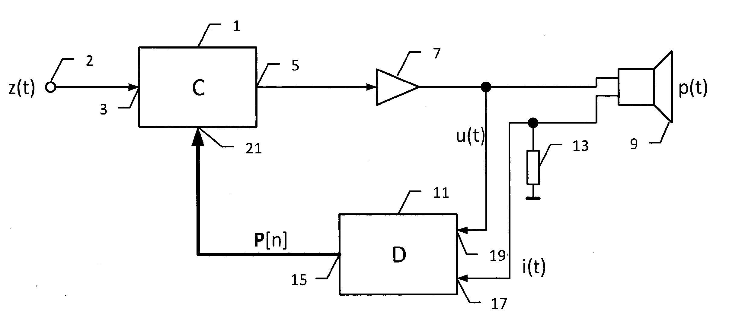
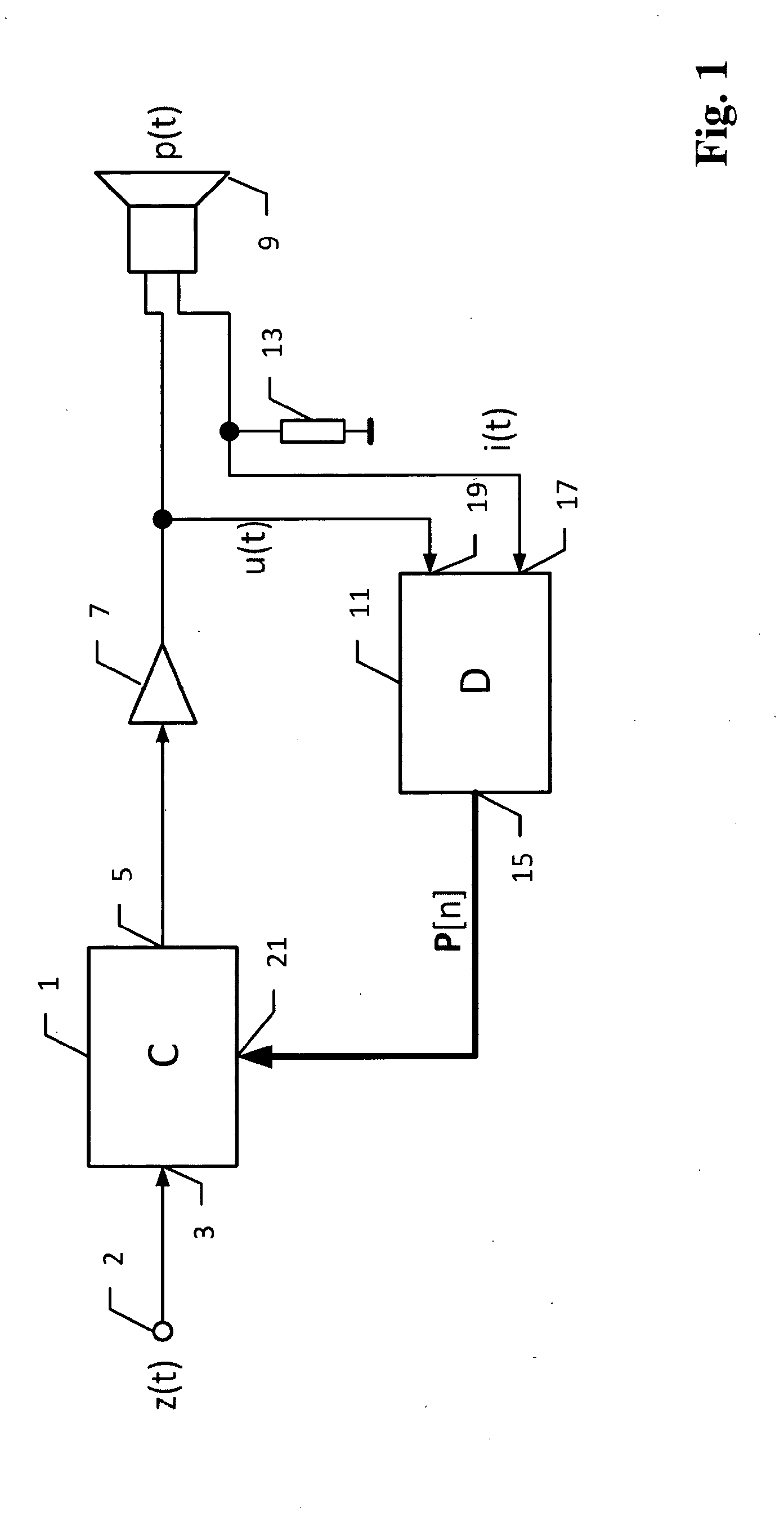
[0066]FIG. 6 shows an embodiment of the detector 11 for determining the instantaneous resistance variation rv(t) and the predicted resistance variation rp(t). A power estimator 53 is provided with measured current signal i(t) and voltage signal u(t) and generates the instantaneous electric input power Pe(t) of the transducer 9 according to Eq. (17). The resistance predictor 58 provided with input power Pe(t) and parameter vector P generates the predicted resistance variation rp(t) and the following integrator 56 generates the instantaneous resistance variation rv(t) according to Eq. (18). The adder 57 provided with the slow time varying parameter Re and resistance variation rv(t) produces the instantaneous voice coil resistance Rat) in accordance with Eq. (23). The variables rp(t), rv(t) and Re,i(t) are suppli...

embodiment 2

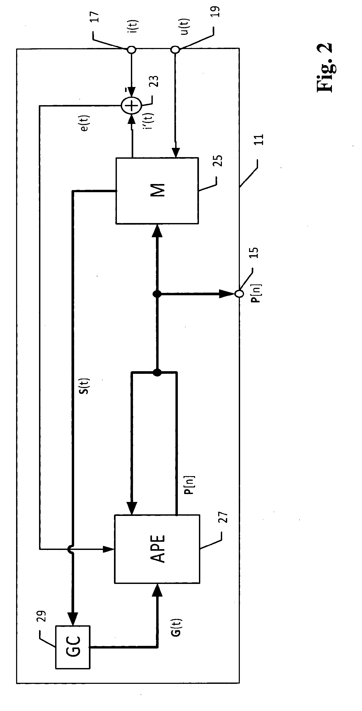
[0086]3. Arrangement , wherein said activator (41) has an input provided with said parameter vector (P[n]), wherein said activator (41) is further configured to: generate a value describing the temporal variance of each parameter in said parameter vector (P[n]); and to generate said activation signal (μ(t)) which deactivates the updating of a parameter having the lowest value of the temporal variance while activating the updating of other parameters having a higher variance.

[0087]4. Arrangement according to embodiment 2 or 3, wherein said activator (41) is provided with the error signal (e(t)) from the error generator (23) or with the parameter vector (P[n]) from said parameter estimator (27), wherein said activator (41) is further configured to: generate an importance value, that describes the contribution of each parameter to the modeling of transducer (9); and to generate said activation signal (μ(t)) which deactivates the estimation of a parameter having an importance value that...

embodiment 7

[0092]8. Arrangement , wherein said compensator (79, 77) comprises: a low-pass filter (79), having an input provided with said control output signal (w(t)) and having an output generating a low-frequency signal (y=(t)) based on said control output signal (w(t)); and a subtracter (77) generating said compensated signal (y(t)) by calculating a difference between said input signal (z(t)) and said low-frequency signal (y=(t)).

[0093]9. Arrangement according to any of the preceding embodiments, wherein said controller (1) contains a gain controller (95), having an input provided with said parameter vector (P[n]) from said parameter input (21) and an output (91) generating a control gain (Gw) which depends on the validity of said parameter vector (P[n]); said controller (1) contains a transfer element (65), having an input provided with said input signal (z(t)) and an output, wherein said parameter vector (P[n]) determines the transfer behavior between the input and the output of the trans...


PUM


Abstract

An arrangement and method for converting an input signal into a mechanical or acoustical output signal by using a transducer and additional means for generating a desired transfer behavior and for protecting said transducer against overload. Transducers of this kind are for example loudspeaker, headphones and other mechanical or acoustical actuators. The additional means comprise a controller, a power amplifier and a detector. The detector identifies parameters of the transducer model if the stimulus provides sufficient excitation of the transducer. The detector permanently identifies time variant properties of the transducer for any stimulus supplied to the transducer. The controller provided with this information generates a desired linear or nonlinear transfer behavior; in particular electric control linearizes, stabilizes and protects the transducer against electric, thermal and mechanical overload at high amplitudes of the input signal.

Description

FIELD OF THE INVENTION[0001]The invention generally relates to an arrangement and a method for converting an input signal z(t) into a mechanical or acoustical output signal p(t) by using a transducer and additional means for generating a desired transfer behavior and for protecting said transducer against overload. Transducers of this kind are loudspeakers, headphones and other mechanical or acoustical actuators. The additional means identify the instantaneous properties of the transducer and generate a desired linear or nonlinear transfer behavior by electric control; in particular linearize, stabilize and protect the transducer against electric, thermal and mechanical overload at high amplitudes of the input signal.DESCRIPTION OF THE RELATED ART[0002]Electro-acoustical transducers have inherent nonlinearities generating instabilities and signal distortion in the output signal p(t) which limit the useable working range. The U.S. Pat. No. 4,709,391 and U.S. Pat. No. 5,438,625 disclo...

Claims


Application Information

Patent Timeline
IPC IPC(8): H04R3/00
CPCH04R3/007H04R3/02H04R3/08H04R29/001
Inventor KLIPPEL, WOLFGANG
Owner KLIPPEL WOLFGANG
Why Eureka
Try Eureka