Soil chemistry sensor

a sensor and soil technology, applied in the field of soil chemistry sensors, can solve problems such as ensuring effective operation of reference electrodes, and achieve the effects of improving internal hydrophobicity, facilitating measurement/monitoring actual levels, and increasing reliability

Active Publication Date: 2015-11-12
PLANT BIOSCI LTD
View PDF1 Cites 29 Cited by
  • Summary
  • Abstract
  • Description
  • Claims
  • Application Information

AI Technical Summary

Benefits of technology

[0010]In some preferred embodiments the second, reference electrode is a double junction electrode, in particular including a second electrode chamber connecting with the first via a second porous plug, preferably also fabricated from a polymer material, in a similar manner to the outer porous reference electrode plug. In practical trials the use of a double junction has been found to provide more stable results (sensing signals) and improved probe lifetime, as well as better protection for the probe overall when used in soil.
[0013]In one preferred implementation a plurality of probes is connected to a shared data logger, which may have a (shared) wireless network connection for exporting captured data, via one or more voltage sensors (one sensor may be multiplexed across a plurality of probes). This facilitates, for example, the soil chemistry to be measured at multiple different depths within the soil, say 30 cm, 60 cm and 90 cm, and / or at multiple different locations within a field. This can provide improved data for more efficient applications of fertiliser by varying the application of fertiliser with location within a field and / or dependent on a measured profile of soil chemistry according to depth. In embodiments a probe or set of probes may include a temperature sensor for adjusting or compensating measurement signals for temperature for improved accuracy.
[0015]The use of a probe, or multiple probes, as described above facilitates measuring / monitoring the actual levels of a plant nutrient in the soil, which can change quite dynamically over time and / or other conditions such as moisture level and the like.
[0016]A low-cost sensor is desirable, for example for developing world applications, and also when wishing to deploy multiple sensors over an area of agricultural land. It has been found that effective electrodes can be fabricated from a disposable plastic pipette tip (for example of, PVC or polypropylene). Preferably the plugs are then formed by solvent-casting a polymer again, for example PVC, as previously described. In such a case it has been found that increased reliability can be obtained by treating the lumen of an electrode in which the plug is being formed so as to increase its internal hydrophobicity. This may be achieved in various ways including, for example, by plasma treatment but in one straightforward approach an emulsion of polydimethylsiloxane, silica filler and non-ionic emulsifier (Dow Corning® Repelcote) is employed.
[0020]The soil chemistry sensors described thus far are capable of measuring the soil chemistry in situ at a certain distance below the surface of the soil, where the distance itself (i.e. depth) is limited by the length of sensor / sensor electrodes. It may be desirable to measure the soil chemistry deeper in a soil structure in a field, and / or to measure the soil chemistry at multiple different depths in a soil structure simultaneously, and / or to obtain real-time soil chemistry data in situ. If real-time measurements indicate that fertilizer needs to be added to the top of the soil, but that the soil is prone to leaching, then a farmer may use the information to decide when to irrigate after applying fertilizer to his crops to minimise the effect of the water washing away the nitrates from near the top of the soil surface.

Problems solved by technology

The inventors have established that for in-situ sensing of soil chemistry, that is sensing by inserting the probe directly into the soil, one key difficulty in practice is ensuring effective operation of the reference electrode.
This is because soil moisture content can vary and with wider spacings the results can be unreliable, becoming overly-dependent on soil moisture level.

Method used


Image

  • Soil chemistry sensor
  • Soil chemistry sensor
  • Soil chemistry sensor

Examples


Embodiment Construction

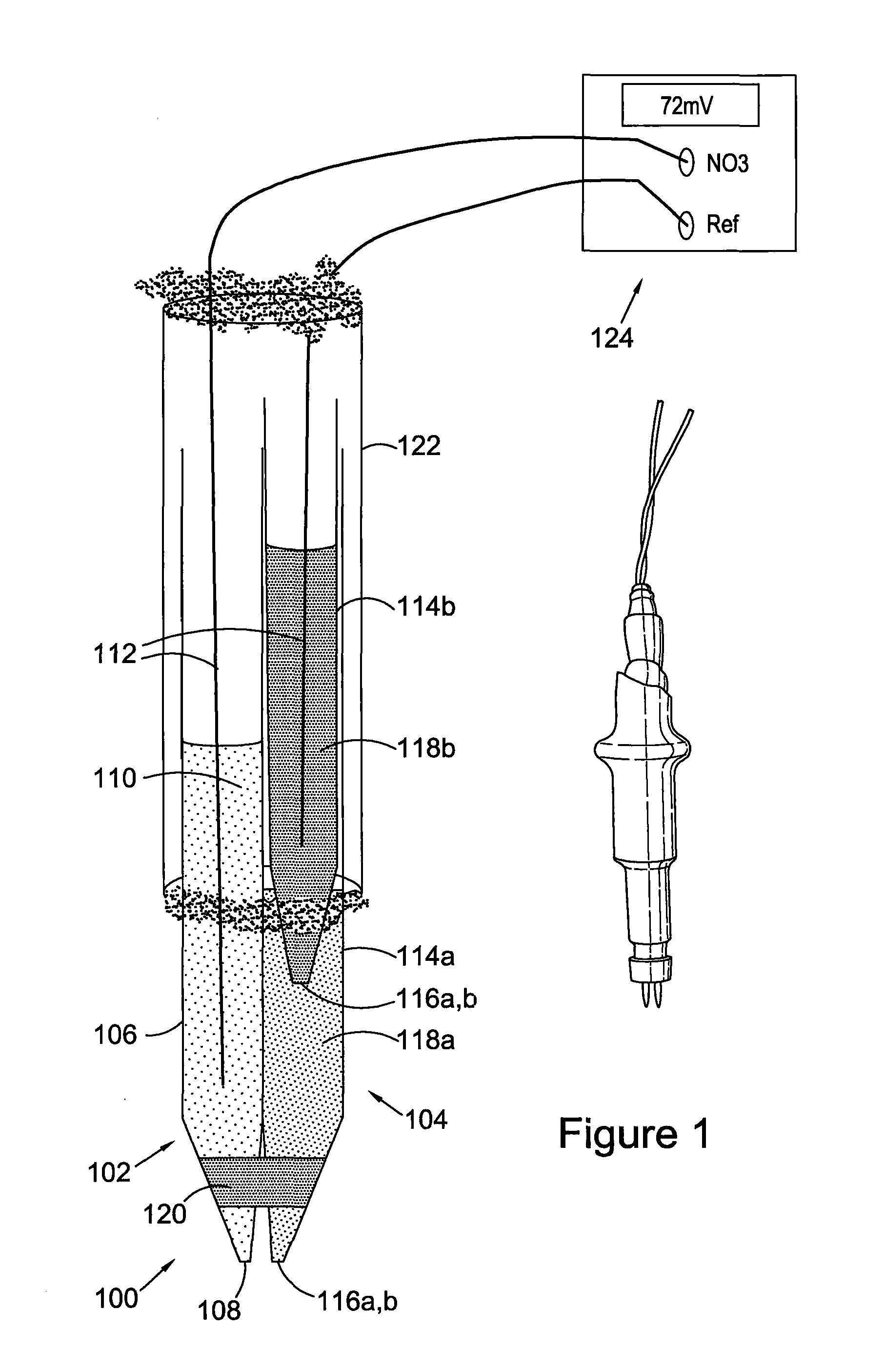
[0055]FIG. 1 shows a nitrate (NO3)-selective soil chemistry sensor 100 according to an embodiment of the invention. The sensor comprises a nitrate-selective electrode 102 and a double junction reference electrode 104. The ion-selective electrode comprises a plastic lumen at 106, in embodiments fabricated from a disposable pipette tip or plastic syringe such as a polypropylene Distritip® syringe, for low cost. An ion-selective membrane 108 is fabricated at the end of the electrode by solvent-casting a polymer such as high molecular weight PVC in combination with an ion carrier. For example for nitrate sensing a suitable ion carrier is tridodecylmethylammonium (TDDMA) nitrate, although additionally or alternatively other ion-selective components may be employed to additionally or alternatively sense other plant nutrients. The membrane composition may be dissolved, for example, in tetrahydrofuran (THF).

[0056]An example ion-selective composition for fabricating a nitrate-selective membr...


PUM

PropertyMeasurementUnit
timeaaaaaaaaaa
depthsaaaaaaaaaa
depthsaaaaaaaaaa

Abstract

We describe a soil chemistry sensor for in-situ soil chemistry sensing, the sensor comprising a probe incorporating a first, ion-selective electrode and a second, reference electrode, wherein said ion-selective electrode comprises a first-electrode housing defining a first lumen having an ion-selective plug towards a distal end, said first-electrode including a first conductor in a first electrolyte, wherein said reference electrode comprises a second electrode housing defining a second lumen having a porous reference electrode plug towards a distal end, said second electrode including a second conductor in a second electrolyte, wherein said ion-selective plug and said porous reference electrode plug are within 10 mm of one another, and wherein said porous reference electrode plug and said ion-selective plug each comprise a polymer.

Description

FIELD OF THE INVENTION[0001]This invention relates to soil chemistry sensors, in particular for sensing nitrate levels, and to the fabrication and use of such sensors.BACKGROUND TO THE INVENTION[0002]Inorganic fertilisers, in particular nitrogen-based fertilisers, have revolutionised agriculture. However effective management of the amount of fertiliser used on land is important for many reasons including economic efficiency and environmental management—excess nitrogen run off from agriculture can enter drinking water causing significant human health concerns, and can also damage fresh water and marine eco-systems. Various techniques are known for monitoring the nitrate level in soil. Typically a soil core is taken, the nitrogen is extracted, and this is then used to predict the amount of nitrogen available to the roots of plants in the soil. However this is a time consuming process typically involving taking a number of soil cores and waiting on average two weeks for the results to ...

Claims


Application Information

Patent Timeline
Patent Type & Authority Applications(United States)
IPC IPC(8): G01N27/403G01N33/24
CPCG01N33/24G01N27/4035G01N27/283G01N27/30G01N27/333
Inventor MILLER, TONYLE BESNERAIS, PIERRE-HENRIMALAURIE, HUGO
Owner PLANT BIOSCI LTD
Why Eureka
Try Eureka