MIMO angle estimation with simultaneous mainlobe jammer cancellation

a mainlobe and estimation technology, applied in the field of radar techniques, can solve the problems of limiting monopulse accuracy, lobe jamming, and reducing the accuracy of monopulse, and achieve the effect of suppressing jamming and sufficient target signal strength

Active Publication Date: 2015-11-12
SRC INC
View PDF0 Cites 29 Cited by
  • Summary
  • Abstract
  • Description
  • Claims
  • Application Information

AI Technical Summary

Benefits of technology

[0012]The present invention addresses the needs described above by providing a system and method for monopulse angle estimation that addresses the drawbacks described above. The system of the present invention applies adaptive jammer cancellation to the angle estimation process without distorting the sum and difference beams and without having to share the receive antenna aperture between the estimation and cancellation processes. The jammer cancellation method of the present invention is more effective than conventional methods because the entire aperture is optimally applied to cancelling the jammer. In this manner, the present invention determines an aperture weight distribution that is optimal for both suppressing jamming and maintaining sufficient target signal strength.

Problems solved by technology

One drawback to the above stated monopulse techniques for estimating the target angle (θ) relative to the antenna boresight is that they fail in the presence of main lobe jamming because the jamming noise renders the values in the look-up table substantially useless.
One drawback associated with this approach is that the two partially overlapped subarrays are composed of different antenna elements, feedlines, and, if digital, A / D converters and receivers.
The cancellation weights reflect these differences and they, in turn, limit the monopulse accuracy.
One drawback to this approach is that it requires two sets of adaptive weights and controls, and in other words, two sets of adaptive beam forming hardware, or for digitized arrays, twice the digital processing, are required.
In particular, the aperture weight distribution appropriate for one function is not appropriate for the other, and so the aperture must be divided in some manner.
In all three jamming cases, however, the angle estimation ratio deteriorates severely with jamming The main reason for this is the loss of a null at the origin in the post adaptive difference beam (FIG. 5).

Method used


Image

  • MIMO angle estimation with simultaneous mainlobe jammer cancellation
  • MIMO angle estimation with simultaneous mainlobe jammer cancellation
  • MIMO angle estimation with simultaneous mainlobe jammer cancellation

Examples


Embodiment Construction

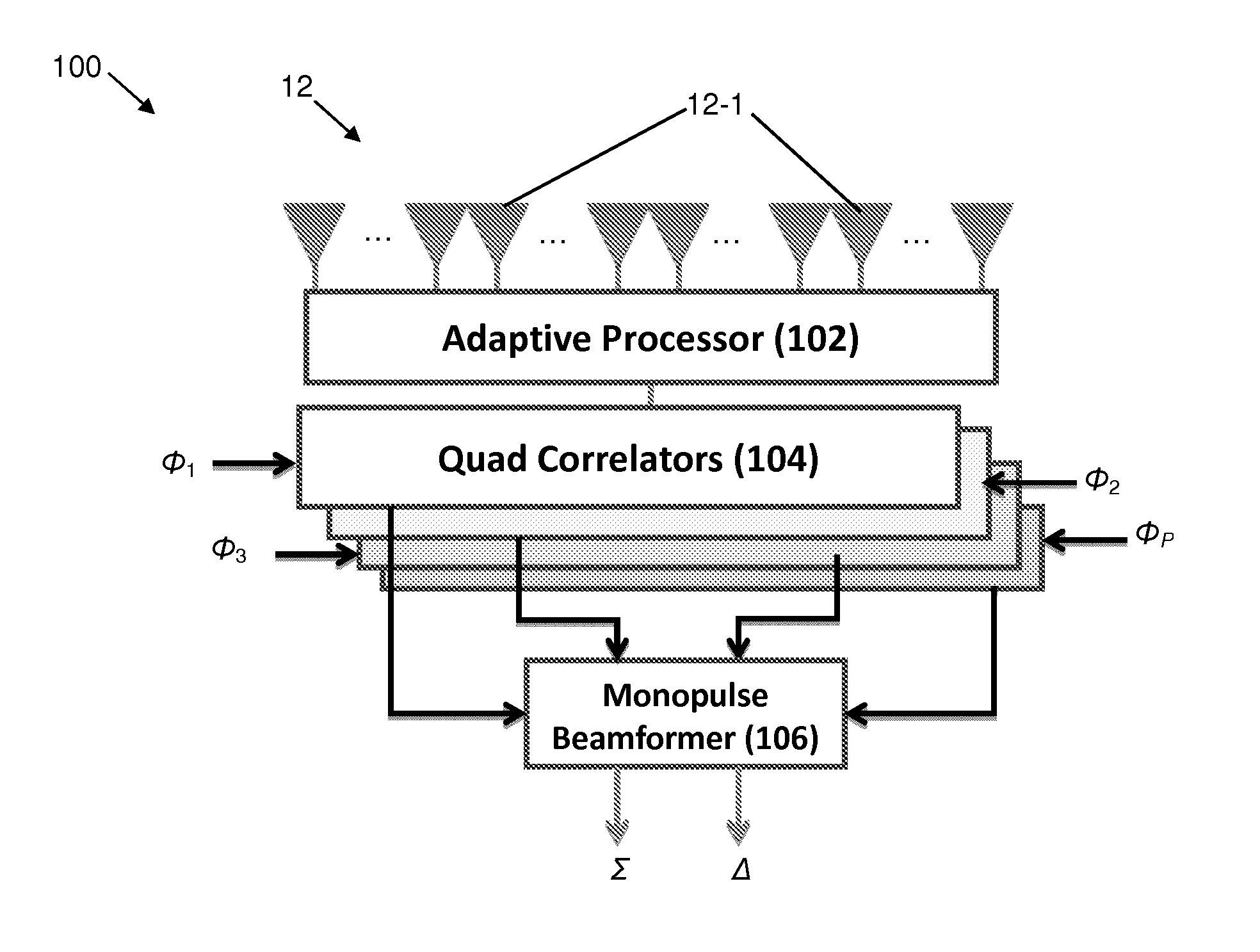
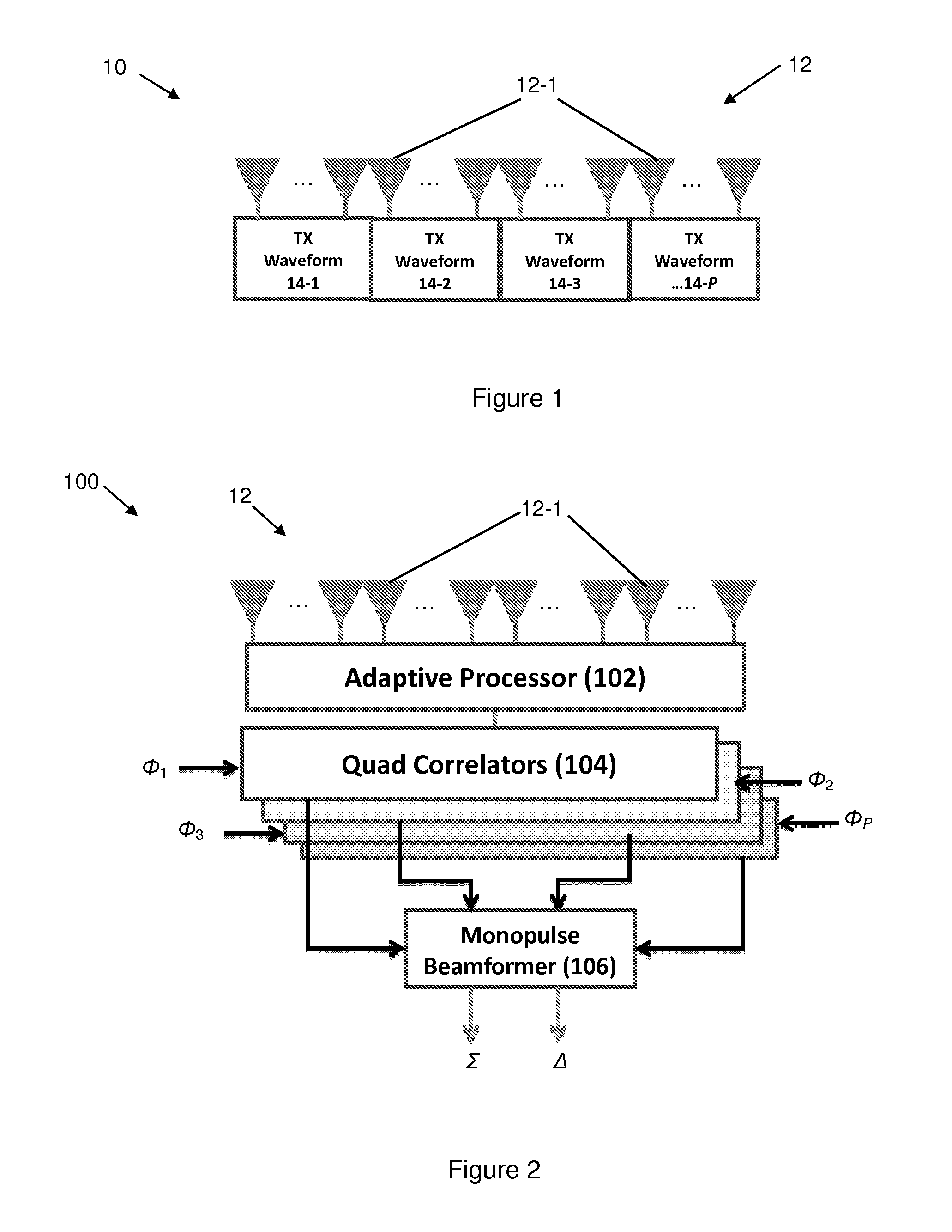
[0026]Reference will now be made in detail to the present exemplary embodiments of the invention, examples of which are illustrated in the accompanying drawings. Wherever possible, the same reference numbers will be used throughout the drawings to refer to the same or like parts. An exemplary embodiment of the receiver of the present invention is shown in FIG. 2, and is designated generally throughout by reference numeral 100.

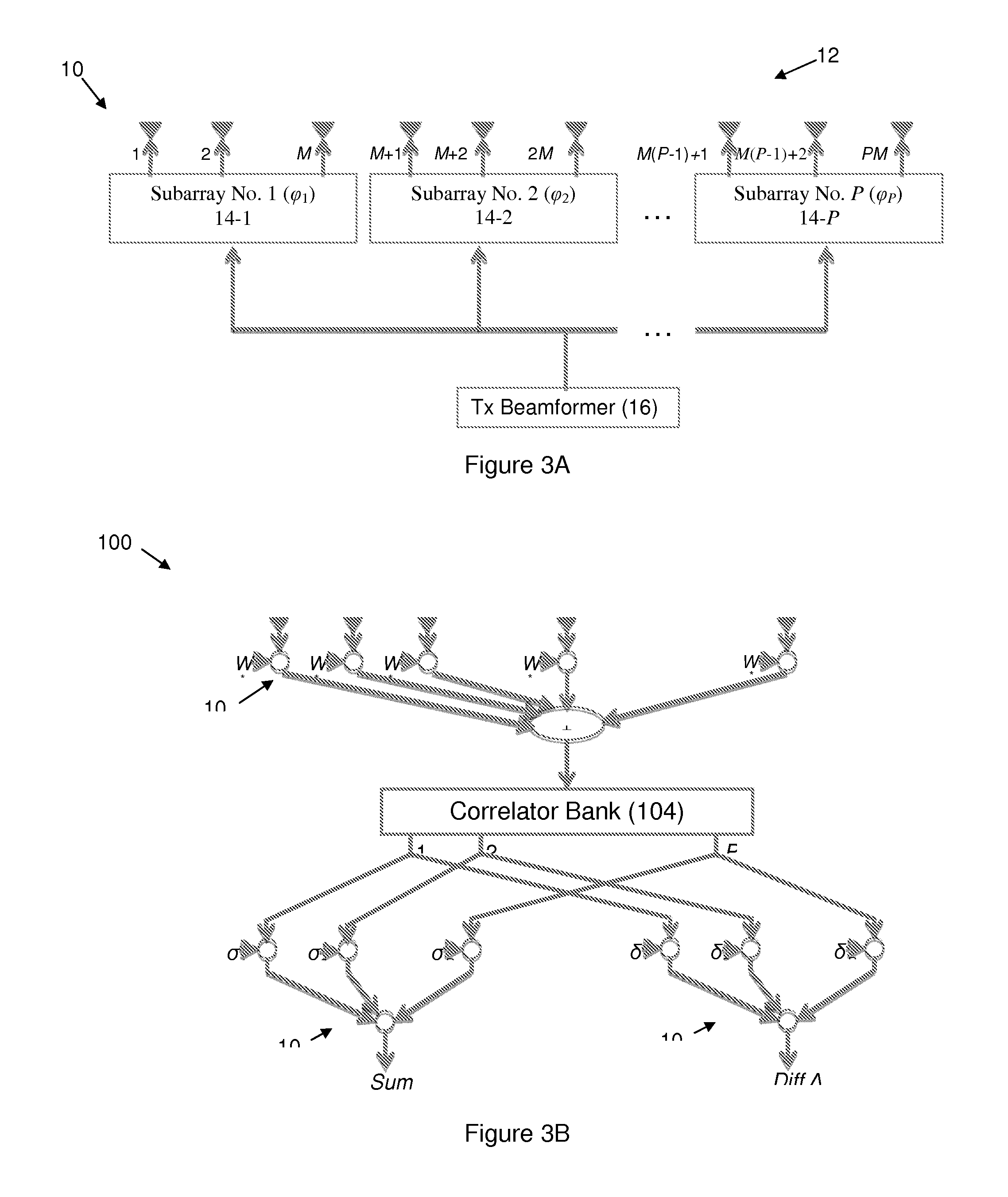
[0027]As embodied herein, and depicted in FIG. 1, a diagrammatic depiction of a transmitter 10 in accordance with the present invention is disclosed. A Multiple Input Multiple Output (MIMO) waveform diversity radar architecture is shown in FIG. 1. The antenna 12 includes a plurality of antenna elements 12-1. These antenna elements 12-1 are divided among a plurality of subapertures 14-1 . . . 14-P, where P is an integer. The term subarray is often used in place of the term subaperture. Each subarray 14 is configured to transmit an orthogonal signal (φ1-φP). As t...


PUM


Abstract

A radar system includes a transmit antenna array having subarrays disposed at predetermined positions. An orthogonal waveform signal is directed to a corresponding one of the subarrays. On receive, an adaptive processor derives a plurality of adaptive weight factors from a plurality of receive signals and applies them to the receive signals to obtain a jammer cancelled signal. That signal is separated into its orthogonal waveform components by passing it through a bank of correlators. The correlator system provides a plurality of unique receive signals substantially corresponding one-to-one to the unique transmit subarrays. The receive beamformer derives an angular estimate of at least one target relative to boresight from the unique receive signals.

Description

BACKGROUND OF THE INVENTION[0001]1. Field of the Invention[0002]The present invention relates generally to radar techniques, and particularly to determining the angular direction of a radar target in a jamming environment.[0003]2. Technical Background[0004]The word “radar” is an acronym for radio detection and ranging that was coined by the U.S. Navy in the 1940s when the technology was in its infancy. Essentially, a radar system is one that alternately transmits radio frequency (RF) signals into a given search volume and then listens for reflections. By properly processing the radar returns, a radar system can determine the direction, range, altitude and / or speed of a target. Nowadays radar is used in a variety of ways. For example, the weatherman uses radar to track rain and snow storms. Police use radar to determine the speed of motorists. Civil aviation uses radar for air traffic control purposes. The military uses radar to track aircraft, ships, terrain and missiles. Needless t...

Claims


Application Information

Patent Timeline
Patent Type & Authority Applications(United States)
IPC IPC(8): G01S7/36G01S13/44G01S7/28G01S13/06
CPCG01S7/4026H01Q3/2605H04K3/228G01S13/36H04B7/086G01S13/4463G01S13/5244H01Q3/2611G01S7/2813G01S7/28G01S7/36G01S13/06G01S13/44
Inventor SCHUMAN, HARVEY K.
Owner SRC INC
Why Eureka
Try Eureka